Method of thermoforming a bladder structure

a bladder and fluid filling technology, applied in the field of thermoforming a bladder structure, can solve the problems of deteriorating overall cushioning of the midsole, reducing the compressibility of the foam, etc., and achieves the effects of improving efficiency, increasing the visibility of the bladder's interior, and reducing labor and cycle times

Inactive Publication Date: 2005-01-04
NIKE INC
View PDF10 Cites 284 Cited by
  • Summary
  • Abstract
  • Description
  • Claims
  • Application Information

AI Technical Summary

Benefits of technology

The bladder formed by the method of the present invention includes an outer enclosing member and an inner core. The outer enclosing member is formed of two sheets of a thermoplastic material that are joined to form a peripheral bond. Located within the outer enclosing member is the core. The core is formed of two fabric layers that are connected by a plurality of connecting members, such as drop yarns. The fabric layers are bonded to the outer enclosing member. A pressurized fluid is also located within the outer enclosing member, thereby placing the connecting members under tension.
Unlike the prior art thermoforming technique of the '451 patent to Skaja et al., the present method has the advantage of locating the seam that joins the two sheets of thermoplastic material in a position that is not centrally located in the bladder sidewall, thereby removing the seam from the area of maximum sidewall flexing and increasing visibility of the bladder's interior. Furthermore, the present method achieves this result using a more efficient manufacturing process than that of the '585 patent. Improved efficiency is achieved by minimizing the required tooling set, i.e., no laminating set or RF tooling set is necessary; lowering labor and cycle times; and permitting more bladders to be formed per unit of material. The present process also improves bladder quality in that lamination welds and bladder dimensions are more consistent.

Problems solved by technology

However, after repeated compressions, the cell structure collapses, resulting in decreased compressibility of the foam.
Thus, the overall cushioning of the midsole deteriorates.

Method used


Image

  • Method of thermoforming a bladder structure
  • Method of thermoforming a bladder structure
  • Method of thermoforming a bladder structure

Examples


Embodiment Construction

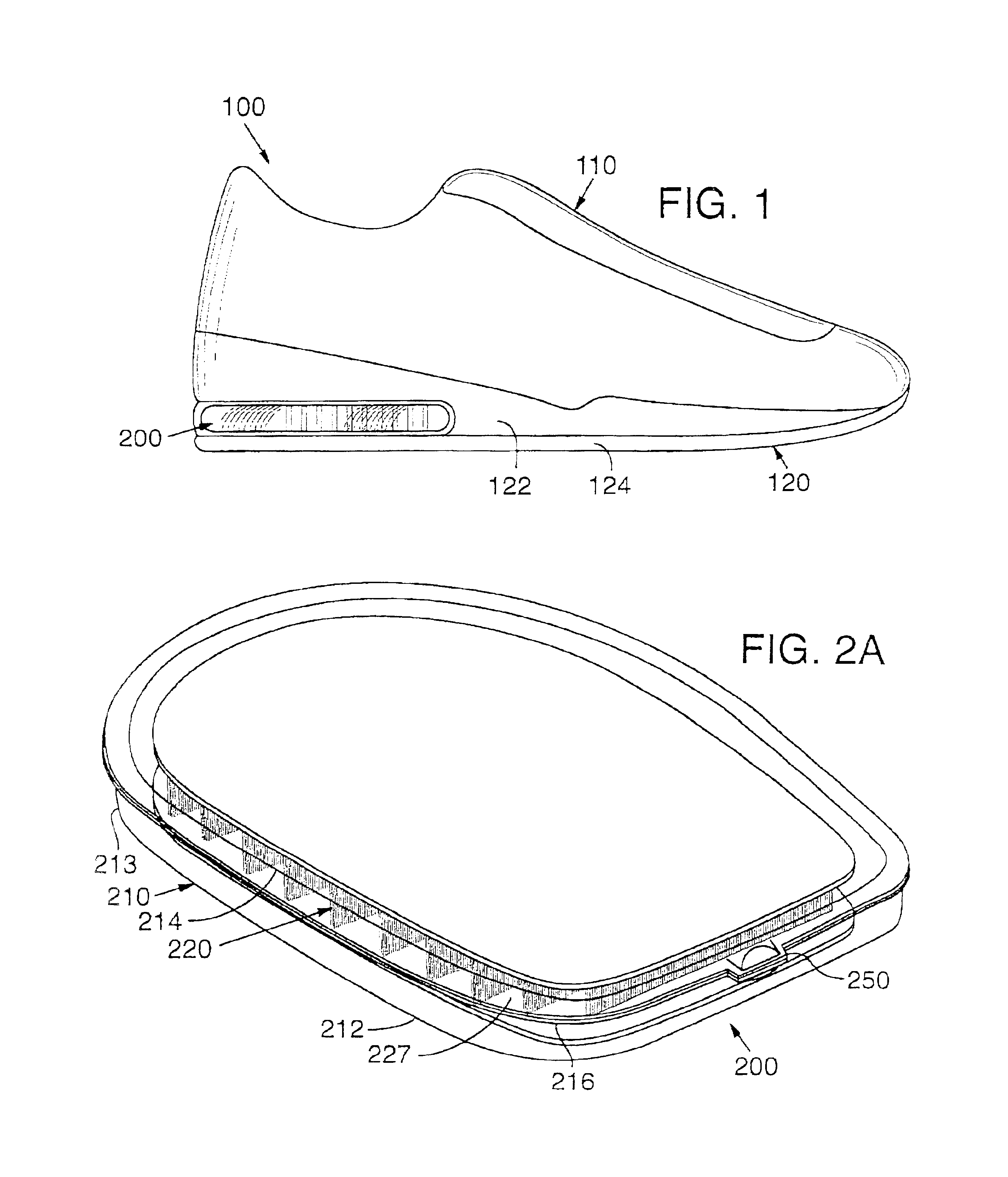
Article of footwear 100, depicted in FIG. 1, includes an upper 110 and a sole structure 120. Upper 110 is configured to receive a foot of a wearer. Sole structure 120, which provides a durable, shock-absorbing medium located between the foot and the ground, is primarily formed of a midsole 122 and an outsole 124. A bladder 200, formed in accordance with the method disclosed below, is secured in the heel area of midsole 122 and above outsole 124. As depicted in FIG. 1, article of footwear 100 is an athletic shoe. Bladder 200 may, however, be utilized in other types of footwear, including dress shoes, sandals, in-line skates, and boots.

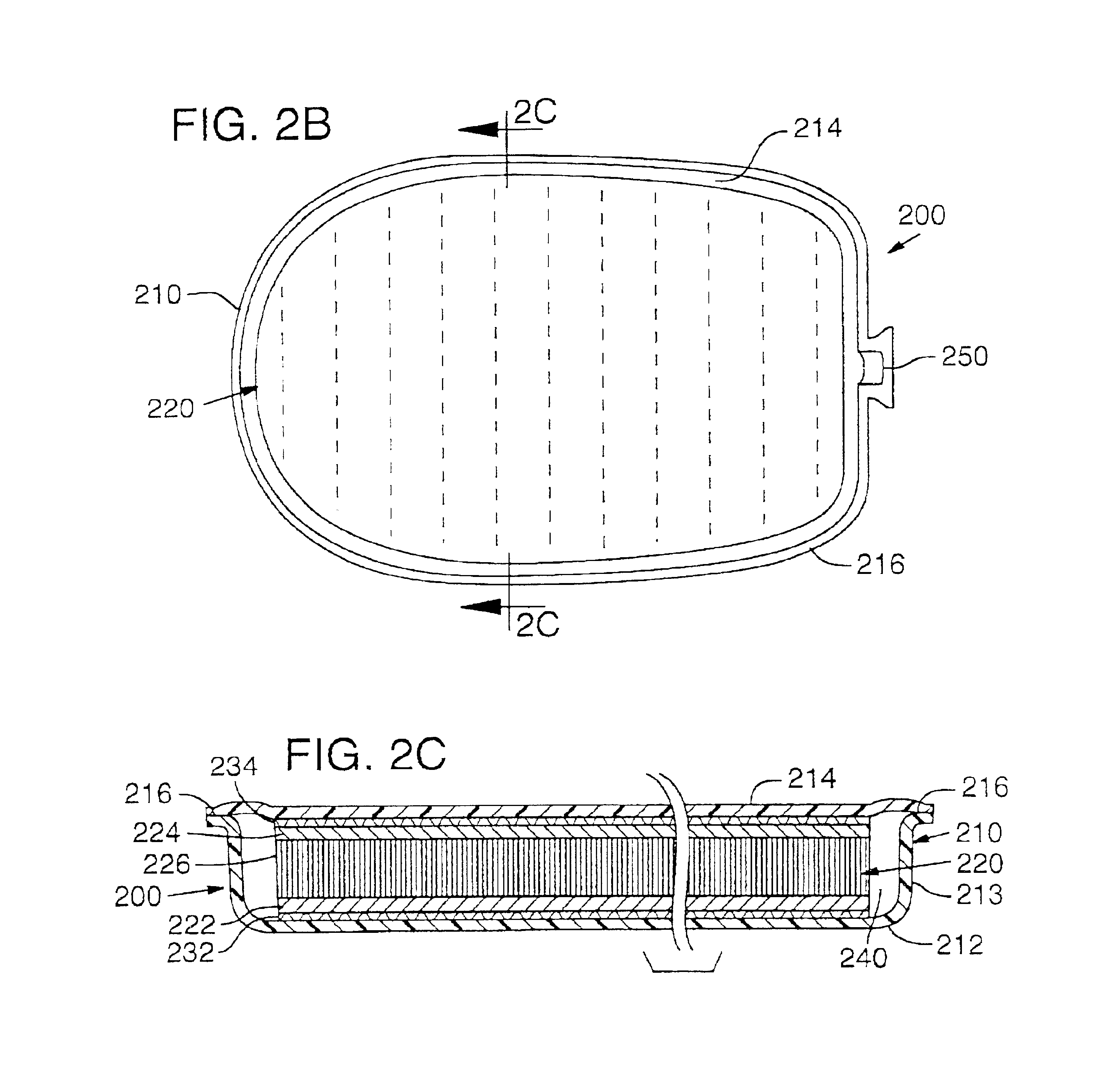
Bladder 200, depicted in FIG. 2, includes an outer enclosing member 210, an inner core 220, a pair of coupling layers 232 and 234, a fluid 240, and an inlet 250. Outer enclosing member 210 is formed of a first sheet 212 and a second sheet 214 that are joined to form a peripheral bond 216. The material forming sheets 212 and 214 may be, for example, five...


PUM

PropertyMeasurementUnit
thicknessaaaaaaaaaa
thicknessaaaaaaaaaa
thicknessaaaaaaaaaa

Abstract

A method for thermoforming a resilient, fluid-filled bladder structure with thermal contact molding is disclosed. The bladder includes two sheets of thermoplastic material that are separated by at least one core formed of two spaced outer layers connected together by a plurality of connecting members. The bladder is formed by bonding the sheets to the core, bonding the sheets to each other around the periphery of the core and forming a sidewall between the sheets in a single mold. A fluid is then inserted into the space bounded by the peripheral bond and the two sheets such that the connecting members are extended.

Description

BACKGROUND OF THE INVENTION1. Field of the InventionThe present invention relates to a method for thermoforming a resilient, fluid-filled bladder for use in a variety of applications, including footwear soles.2. Description of Background ArtFootwear is divided into two general parts, an upper and a sole. The upper is designed to comfortably enclose the foot and the sole provides traction, protection, and a durable wear surface. The considerable forces generated in athletics require that the sole of footwear provide enhanced protection and shock absorption for the foot and leg. Accordingly, the sole of athletic footwear typically includes several layers, including a resilient, shock-absorbent midsole and a ground-contacting outsole which provides both durability and traction.Such midsoles have been formed of conventional foam materials, for example, ethylene vinyl acetate or polyurethane which compress resiliently under an applied load and provide cushioning. Outsoles have been made ...

Claims


Application Information

Patent Timeline
Patent Type & Authority Patents(United States)
IPC IPC(8): A43B13/20A43B13/18B29D31/518B29D31/50B29D35/14
CPCA43B13/20B29D35/14B29D35/148D04B21/16Y10T156/1002D10B2403/021Y10T156/1043Y10T428/231D10B2403/0122Y02P70/62
Inventor RAPAPORT, ZVI
Owner NIKE INC
Why Eureka
Try Eureka