Artificial limb assembly having microprocessor-controlled vacuum pump

a technology of microprocessor control and vacuum pump, which is applied in the field of artificial limbs with microprocessor controlled vacuum pump, can solve the problems of user experience, no vacuum can be generated, and individual problems of the limb, so as to reduce the number of pump cycles and good sealing

Inactive Publication Date: 2007-09-13
SMITH JAMES E +1
View PDF8 Cites 38 Cited by
  • Summary
  • Abstract
  • Description
  • Claims
  • Application Information

AI Technical Summary

Benefits of technology

[0017] Preferred forms of the invention may also include a sealing means adapted to maintain separation between the interior of the socket assembly to which the vacuum pressure is applied and the outside atmosphere. This can be accomplished using a variety of means including customized synthetic resin sleeves, conventional sealing sleeves, gators, tape, and elastic bands. A good sealing means will decrease the number of pump cycles the vacuum pump will initiate.

Problems solved by technology

Residual limbs may also have individual problems owing to scarring, skin grafts, bony protuberances, uneven volume, neuroma, pain, or edema.
While prior motion or weight-operated vacuum prosthetic devices have achieved substantial success in the market place, they suffer from a number of drawbacks.
First, during periods where the amputee is at rest, no vacuum can be generated.
Thus, the user may experience a situation where the device becomes loose or even detaches from the residual limb, owing to inactivity over a period of time.
Additionally, there is generally no way to periodically or continuously monitor the actual negative pressure conditions within the socket, so that the magnitude of negative pressure may vary over wide limits.
It is also generally known that residual limbs tend to lose volume over the course of the day if the negative pressure within the socket decreases beyond a certain threshold.
This can be a problem during periods of rest in these weight or motion operated devices.
Finally, these prior motion or weight-activated devices are limited to particular applications such as specific types or brands of prosthetics and certain residual limb lengths.

Method used


Image

  • Artificial limb assembly having microprocessor-controlled vacuum pump
  • Artificial limb assembly having microprocessor-controlled vacuum pump
  • Artificial limb assembly having microprocessor-controlled vacuum pump

Examples


Embodiment Construction

Embodiment of FIGS. 1-3

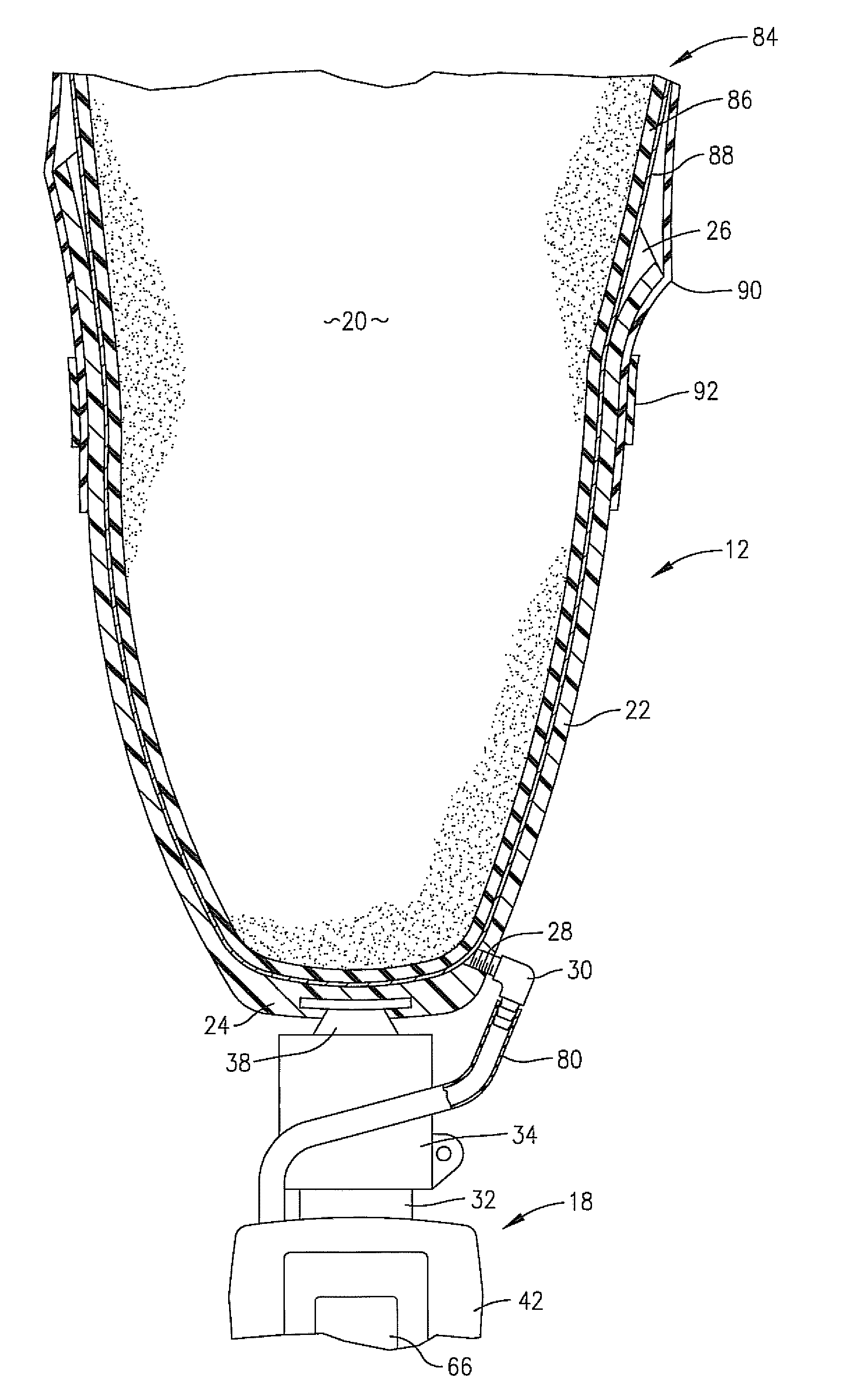
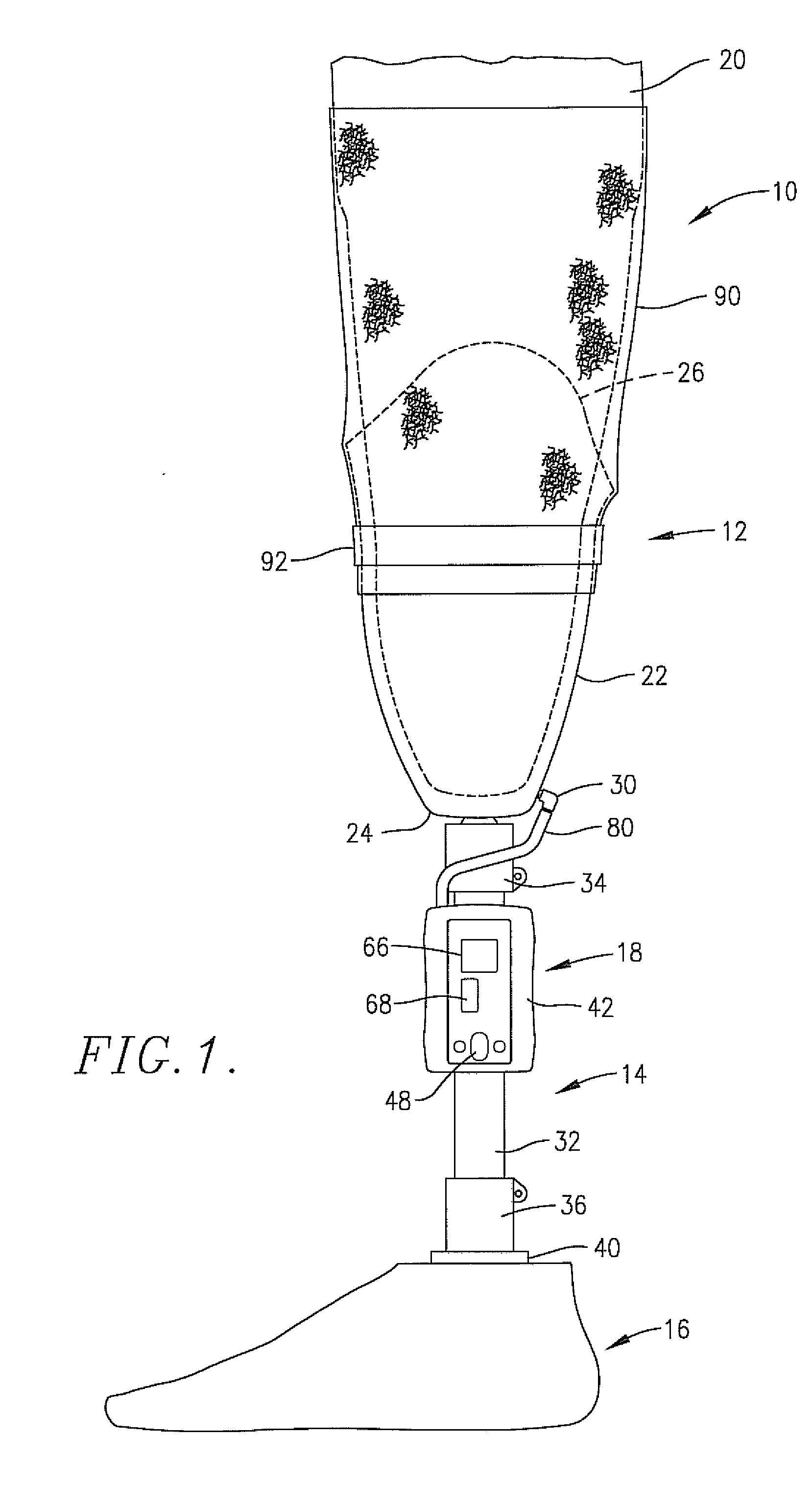
[0026] Turning now to the drawings, an artificial limb assembly 10 is depicted in FIG. 1 and broadly includes a socket assembly 12, a pylon 14, a prosthetic foot 16, and a vacuum pump and control assembly 18. The limb assembly 10 is adapted to be coupled with a residual limb 20, in this case, the residuum of a below-the-knee amputation. It will be appreciated, however, that the invention is not limited to this specific type of artificial limb assembly, but can be used for other varieties, e.g., above-tie-knee amputations or for artificial arm assemblies.

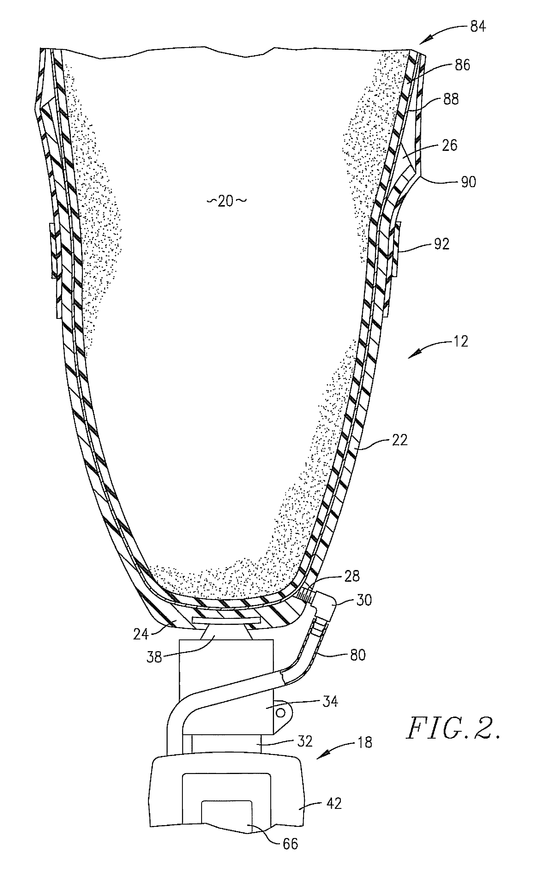
[0027] The socket assembly 12 is best illustrated in FIG. 2, where it will be seen that it includes an upright, open-top relatively rigid socket 22 presenting a lower closed-end 24 and an upper margin 26. It will also be seen that the socket 12 includes a threaded bore 28 receiving a threaded pneumatic nipple 30, which is important for purposes to be described. Generally, the socket 22 would be custom-prepared...


PUM


Abstract

Vacuum-assist artificial limb assemblies (10, 94) are provided having a socket (22, 104) for receiving a residual limb (20). The assemblies (10, 94) include a vacuum pump and control assembly (18, 100, 102) with a selectively operable vacuum pump (72, 116) controlled by a microprocessor (44, 102). The microprocessor (44, 102) is also connected with an on-off switch (48, 146), pressure adjust buttons (68, 148), a pressure read-out (66, 150), and an optional alarm (70). In use, a pressure transducer (74) in communication with the interior of socket (22, 104) and coupled with microprocessor (44, 102) monitors negative pressure conditions within the socket (22, 104), and the microprocessor (44, 102) operates pump (72, 116) in response to transducer pressure signals. In this manner, the vacuum-assist operation of assemblies (10, 104) is essentially automatic. In one embodiment, a vacuumization assembly (100) including an air induction component (114) and a mated vacuum pump component (116) are located within a housing (108) forming a part of socket (104), and a separate controller (102) is coupled with vacuum component (116) for control thereof.

Description

RELATED APPLICATIONS [0001] This application is a continuation-in-part of U.S. patent application Ser. No. 11 / 081,205, filed Mar. 16, 2005, and this application is incorporated by reference herein.BACKGROUND OF THE INVENTION [0002] 1. Field of the Invention [0003] The present invention is broadly concerned with improved prosthetic devices such as artificial limb assemblies of the type incorporating a vacuum pump in order to establish negative pressure conditions serving to securely attach the devices to residual limbs. More particularly, the invention is concerned with such prosthetic devices, and methods of operation thereof, wherein the devices include a vacuum-generating assembly including a powered vacuum source as well as a digital control assembly (e.g., a microprocessor) which is programmed to develop and maintain preselected negative pressure conditions. The digital control apparatus may be permanently mounted upon a portion of the artificial limb assembly (e.g., a pylon) or...

Claims


Application Information

Patent Timeline
Patent Type & Authority Applications(United States)
IPC IPC(8): A61F2/74A61F2/80
CPCA61F2/60A61F2/68A61F2/76A61F2/80A61F2002/701A61F2002/802A61F2002/742A61F2002/748A61F2002/7655A61F2002/769A61F2002/7837A61F2002/704A61F2/70A61F2002/807A61F2/742A61F2/748
Inventor NACHBAR, THURE
Owner SMITH JAMES E
Why Eureka
Try Eureka