Engine cooling apparatus

a technology for cooling apparatuses and engines, applied in the direction of engine cooling apparatuses, liquid cooling, cylinders, etc., can solve the problem of increasing the amount of coolant, and achieve the effect of effective warming up and cooling the engin

Inactive Publication Date: 2007-12-27
TOYOTA JIDOSHA KK
View PDF2 Cites 5 Cited by
  • Summary
  • Abstract
  • Description
  • Claims
  • Application Information

AI Technical Summary

Benefits of technology

[0018] According to the invention, immediately after the coolant passes through a part of the block water jacket formed in the cylinder block, the coolant flows into the head water

Problems solved by technology

Also, the amount of co

Method used


Image

  • Engine cooling apparatus
  • Engine cooling apparatus
  • Engine cooling apparatus

Examples


Embodiment Construction

[0033] In the following description, the present invention will be described in more detail in terms of exemplary embodiments.

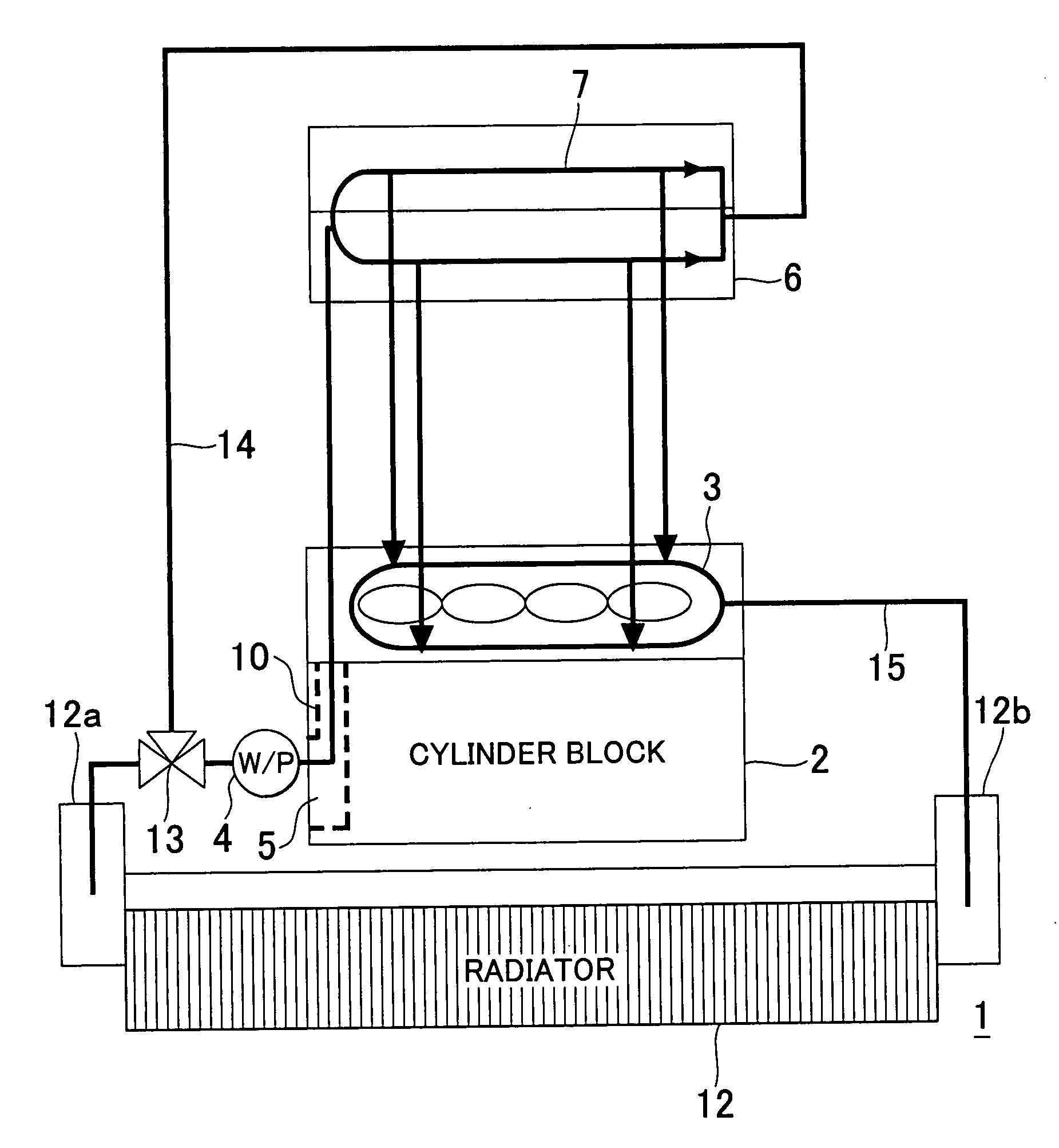
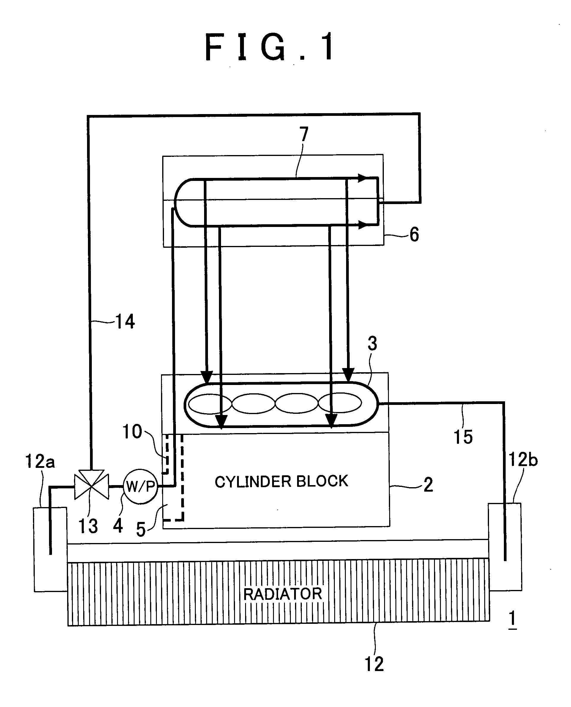
[0034]FIG. 1 is a schematic diagram showing a four-cylinder engine 1 provided with an engine cooling apparatus according to an embodiment of the invention. In a cylinder block 2 that constitutes the engine 1, a block water jacket 3 is formed. The block water jacket 3 includes a coolant inlet 5 through which coolant supplied from a water pump 4 is introduced into the block water jacket 3. In a cylinder head 6, a head water jacket 7 is formed.

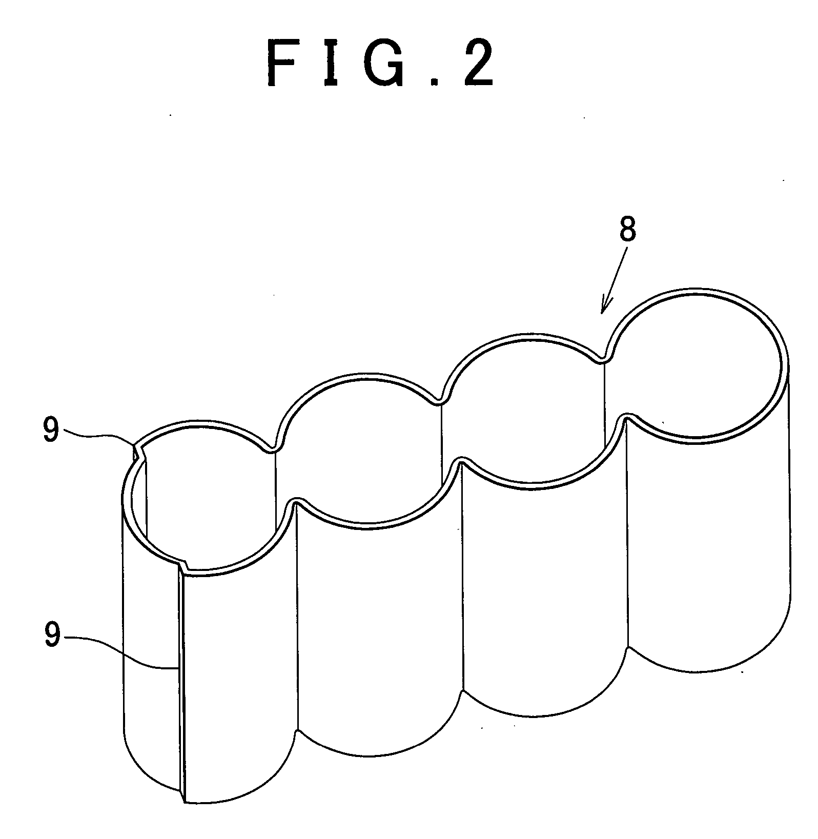
[0035]FIG. 2 is a perspective view showing a water jacket spacer 8 fitted into the block water jacket 3. FIG. 3A is a plan view showing the water jacket spacer 8. FIG. 3B is a plan view showing the cylinder block 2. FIG. 3C is a plan view showing the cylinder block 2 in which the water jacket spacer 8 is fitted into the block water jacket 3. Flow-directing plates 9 are formed integrally with the water jacket spacer 8. In...


PUM


Abstract

An engine cooling apparatus includes a coolant inlet of a block water jacket formed in a cylinder block, wherein coolant is introduced into the block water jacket through the coolant inlet, a flow-directing plate that is disposed in the block water jacket at a position downstream of the coolant inlet, and that directs the coolant, which has been introduced into the block water jacket through the coolant inlet, toward a head water jacket and a control portion that controls inflow of the coolant from the head water jacket into the block water jacket.

Description

INCORPORATION BY REFERENCE [0001] The disclosure of Japanese Patent Application No. 2006-156068 filed on Jun. 5, 2006, including the specification, drawings and abstract is incorporated herein by reference in its entirety. BACKGROUND OF THE INVENTION [0002] 1. Field of the Invention [0003] The invention relates to an engine cooling apparatus that effectively warms and cools the engine. [0004] 2. Description of the Related Art [0005] When warming-up has not been completed, for example, great friction is caused in an engine. Therefore, the warming-up needs to be quickly completed. In particular, components having slide portions, such as cylinder bores, pistons, and a crankshaft, need to be quickly warmed to efficiently operate the engine. In an ordinary engine, when air-fuel mixture starts to be ignited in the cylinder, engine components such as a cylinder block and a cylinder head, and engine oil that is circulated in oil passages formed in the engine components, and coolant that is ...

Claims


Application Information

Patent Timeline
IPC IPC(8): F01P9/02
CPCF01P2003/028F01P3/02
Inventor HAYASHI, KUNIHIKOKOBAYASHI, HIDEOARISAWA, KATUHIKOYAMADA, KENICHIYAMASHITA, YOSHIO
Owner TOYOTA JIDOSHA KK
Why Eureka
Try Eureka