
Backlight assembly, and liquid crystal display module and liquid crystal display device having the same

a liquid crystal display and backlight assembly technology, applied in the direction of lighting and heating apparatus, planar/plate-like light guides, instruments, etc., can solve the problems of reducing the stability and reliability of external devices, lcd devices tend to become larger and heavier, and the image quality of lcd modules and devices will deteriorate, so as to improve the shape and structure of lights.

Active Publication Date: 2011-12-01
SAMSUNG DISPLAY CO LTD
View PDF14 Cites 83 Cited by
  • Summary
  • Abstract
  • Description
  • Claims
  • Application Information

AI Technical Summary

Benefits of technology

[0013]An exemplary embodiment of the invention provides a light and compact liquid crystal display (“LCD”) device, by improving the shape and structure of a light guide plate (“LGP”) support.
[0014]Another exemplary embodiment of the invention provides an LCD module and an LCD device with improved quality, by effectively dissipating heat originated from light sources of the LCD module through the LGP support.
[0015]Still another exemplary embodiment of the invention provides a thin and light LCD device with improved structure for installation of external components to the LCD device for manufacturing the LCD device with more stability and endurance.
[0016]A further exemplary embodiment of the invention provides the LCD device including additional elements which can be easily mounted and replaced, and a reduced thickness and size, partly owing to improvements in a mounting structure of the additional elements attached to the LCD module and in a shape of the lower case of the LCD device.
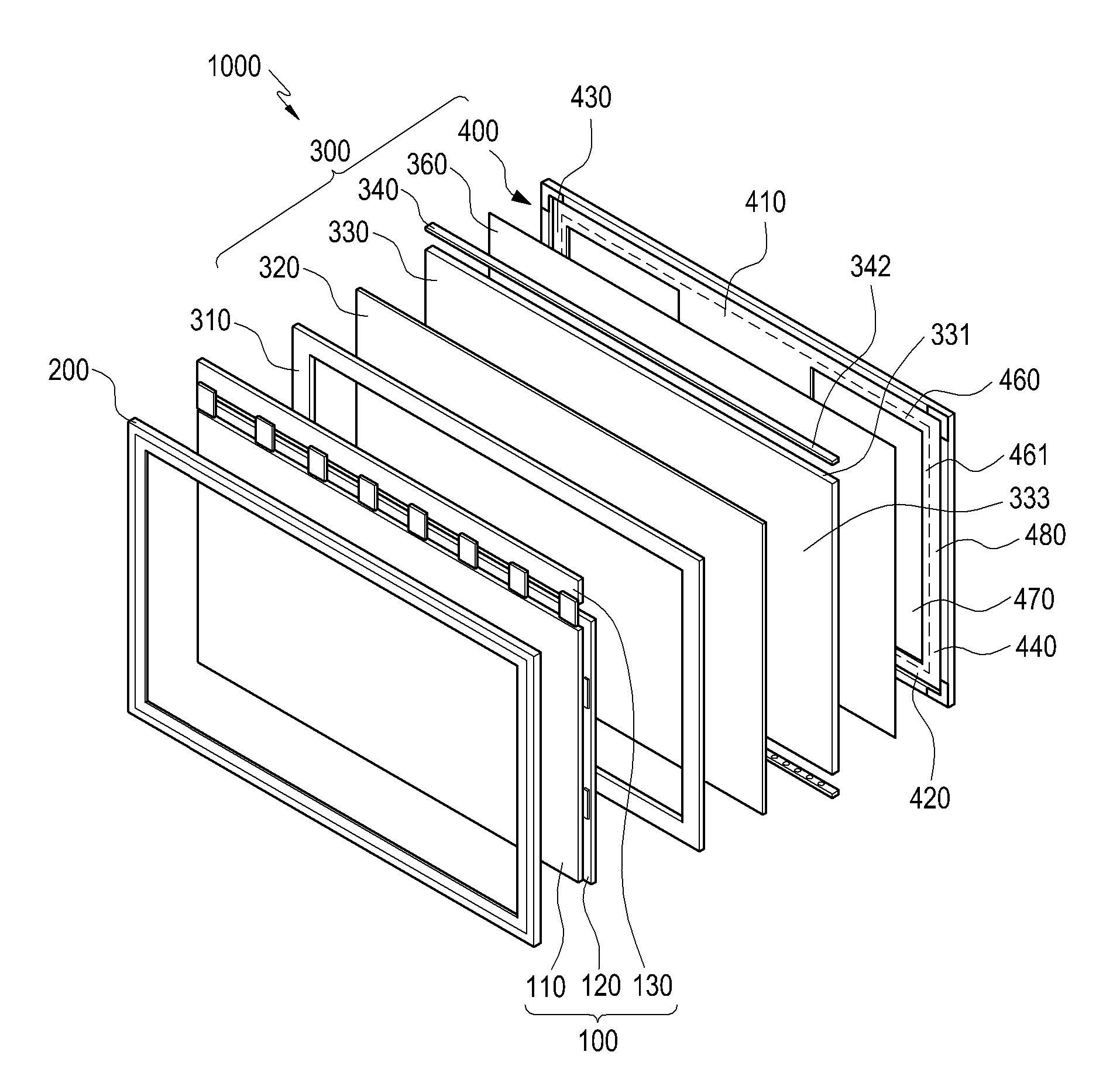
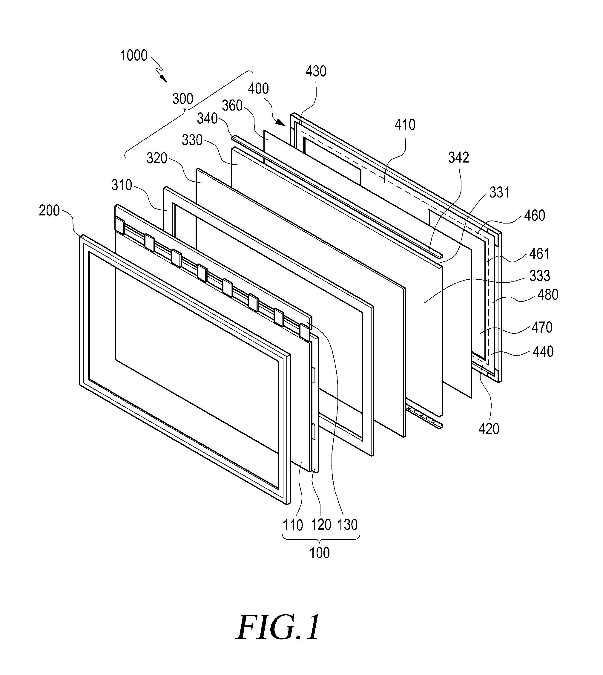
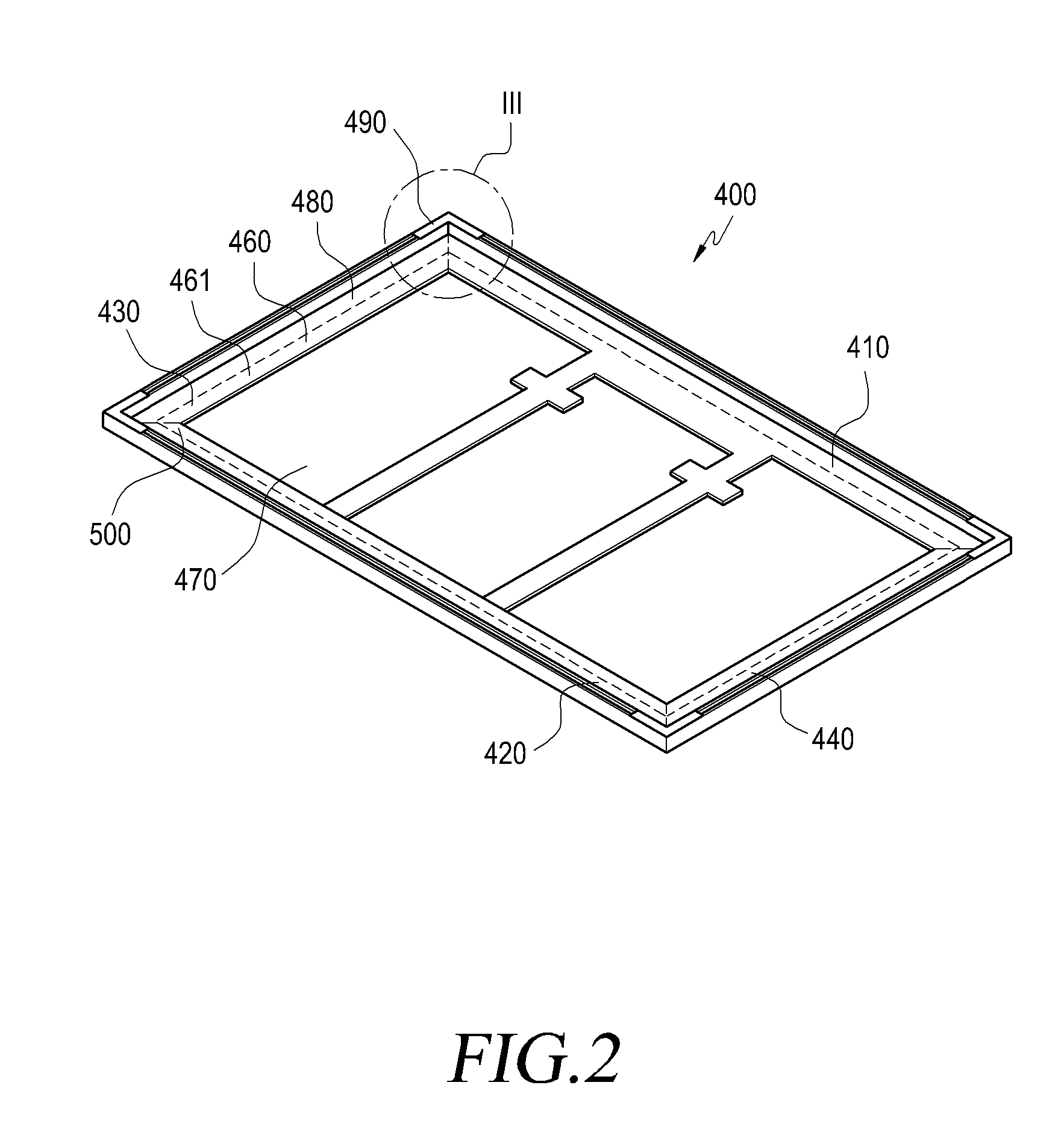
[0021]The plurality of LGP supporting pieces make a closed square LGP support and form an opening at the internal space of the LGP support. A reflector additionally located between the LGP support and the LGP helps even distribution of light within the LGP while the reflector is exposed to an outer side of the LGP support through the opening. An opposing surface of the LGP supporting surface is also exposed to outside of the LGP support. The planar area of the reflector is similar to a planar area of the bottom of the LGP, and from about 30 percent to about 90 percent of the area of the reflector may be exposed to the outside of the LGP support. In other words, about 10 percent to about 70 percent of the area of the LGP may be supported by the LGP support.

Problems solved by technology

However, since more light sources are required as the dimension of the liquid crystal module and device increases, and since a narrower thermal path is provided as the thickness of the liquid crystal module and device decreases, the image quality of the LCD module and device will deteriorate owing to excessive heat.
Here, it is appreciated that since the external device needs additional parts for mounting on the lower case, the LCD device tends to become larger and heavier.
Moreover, such a larger dimension and weight of the LCD device may often decrease stability and reliability of the external device, so simplification of mounting structure of the LCD device is essentially required.
Further, even though the LCD device manufacturer makes a change in the depth of the lower case depending upon the location of the additional element, the lower case is combined with the upper case with constant interval between the cases throughout the LCD module; hence, limitation is caused in reducing the thickness of the LCD device.
Still further, the manufacturing process becomes more complicated for those LCD device manufacturers as the lower cases becomes larger in some applications such as in a large sized television set.

Method used


Image

  • Backlight assembly, and liquid crystal display module and liquid crystal display device having the same
  • Backlight assembly, and liquid crystal display module and liquid crystal display device having the same
  • Backlight assembly, and liquid crystal display module and liquid crystal display device having the same

Examples


Embodiment Construction

[0058]The invention is described more fully hereinafter with reference to the accompanying drawings, in which exemplary embodiments of the invention are shown. This invention may, however, be embodied in many different forms and should not be construed as limited to the exemplary embodiments set forth herein. Rather, these embodiments are provided so that this disclosure will be thorough and complete, and will fully convey the scope of the invention to those skilled in the art. In the drawings, the size and relative sizes of layers and regions may be exaggerated for clarity.

[0059]It will be understood that when an element or layer is referred to as being “on,”“connected to” or “coupled to” another element or layer, the element or layer can be directly on, connected or coupled to another element or layer or intervening elements or layers. In contrast, when an element is referred to as being “directly on,”“directly connected to” or “directly coupled to” another element or layer, there...


PUM


Abstract

A liquid crystal display (“LCD”) module includes a backlight assembly emitting light, a LCD panel overlapping the backlight assembly, and an upper cover. The backlight includes a light source module emitting the light, a light guide plate (“LGP”) including edges and a middle portion, and a LGP support overlapping the edges of the LGP. The LGP support includes a plurality of LGP supporting pieces connected to each other so as to form a polygonal shape, each of the LGP supporting pieces including a LGP supporting portion including a LGP supporting surface overlapping the edges of the LGP, and the LGP supporting surfaces of each of the LGP supporting pieces of the LGP support are placed on a same plane. Opposing LGP supporting pieces are interconnected by an LCD module mounting member.

Description

[0001]This application claims priority to Korean Patent Application filed on May 28, 2010 and assigned Serial No. 10-2010-0050335, and all the benefits accruing therefrom under 35 U.S.C. §119, the entire disclosure of which is hereby incorporated by reference.BACKGROUND OF THE INVENTION[0002]1. Field of the Invention[0003]The invention relates generally to a liquid crystal display (“LCD”) device, an LCD module and a backlight assembly of the LCD module.[0004]2. Description of the Related Art[0005]Conventionally, the LCD module has an LCD panel displaying images in response to electrical signals provided thereto, according to the change in arrangement of liquid crystal molecules and light transmittance, a backlight assembly supplying light to the LCD panel, and covers supporting and fixing the LCD panel and the backlight assembly. The LCD module is fixedly attached to a separate case, and provided to ultimate customers as the LCD device.[0006]The LCD module is used in various kinds o...

Claims


Application Information

Patent Timeline
IPC IPC(8): G02F1/13357F21V13/02F21V8/00
CPCG02B6/0088G02B6/0091G02F1/133308G02F2001/133328G02F1/133615G02F2001/133314G02F1/133608G02F1/133314G02F1/133328G02B6/0055G02B6/0085G02F1/133382G02F1/133524G02F1/133553G02F1/1336G02F1/133605G02F1/133606G02F1/13332
Inventor BAE, HYUN-CHULLEE, JAE-SANGCHOI, SEONG-SIKKWAK, HEE-JUNELEE, SANG-HYEOK
Owner SAMSUNG DISPLAY CO LTD
Learn More