Substrate lift mechanism and reactor including same

a technology of lift mechanism and substrate, which is applied in the direction of chemically reactive gas, coating, crystal growth process, etc., can solve the problems of reactors employing such techniques that exhibit undesired gas flow between the reaction region and deposition and/or corrosion of the reactor within the substrate transfer region, and the reactor volume can be relatively small, less complex, and reliable

Active Publication Date: 2020-09-08
ASM IP HLDG BV
View PDF3986 Cites 146 Cited by
  • Summary
  • Abstract
  • Description
  • Claims
  • Application Information

AI Technical Summary

Benefits of technology

[0006]Various embodiments of the present disclosure provide an improved method and apparatus for processing and transferring substrates. As set forth in more detail below, various systems and methods provide a reactor and / or use a method that can process substrates within a region and transfer substrates to / from the same region within a reactor. In other words, the reactor can include a reaction chamber including a common processing and transfer region. Accordingly, the overall reactor volume can be relatively small, the reactor can be less complex, more reliable, less expensive, and easier to maintain and / or process substrates in a reduced amount of time and / or in a less expensive manner.
[0007]In accordance with at least one exemplary embodiment of the disclosure, a reactor, which includes a common substrate processing and transfer region, includes a reaction chamber comprising a reaction region, a susceptor having a top surface within the reaction region, and a substrate lift mechanism. The substrate lift mechanism can include at least one lift pin, a lift pin support member that engages to (e.g., removably) couple to the at least one pin, and a movable shaft coupled to the lift pin support member. The substrate lift mechanism causes the at least one lift pin to extend above the susceptor surface. In accordance with various aspects of these embodiments, the moveable shaft moves in a vertical direction. The distance that the movable shaft and the lift pins move during a substrate transfer process can range from about 5 mm to about 25 mm, about 10 mm to about 20 mm, or be about 17 mm. In accordance with further aspects of these embodiments, the susceptor includes a center region and a peripheral region. A width of the center region can be greater than a width of the peripheral region. Such a design can facilitate forming the susceptor with a relatively small peripheral width, which in turn can facilitate use of the common region for both substrate processing and transfer. The reactor can further include a rotatable shaft and a susceptor support coupled to the rotatable shaft. The susceptor is coupled to the susceptor support, such that rotational movement of the rotatable shaft is translated to the susceptor. In accordance with various examples of these embodiments, an opening within the reaction chamber, to transfer substrates into and out of the reaction chamber, resides above a top surface of the susceptor when the susceptor is in a processing position.

Problems solved by technology

Although such techniques work relatively well to place substrates within and remove substrates from a reaction space within the reactor, mechanisms to move the susceptor and the lift pins are relatively complex.
In addition, reactors employing such techniques can exhibit undesired gas flow between the reaction region and the substrate transfer region—especially during substrate processing.
The undesired gas flow can lead to deposition and / or corrosion of the reactor within the substrate transfer region.
Furthermore, the volumes of such reactors are relatively large to accommodate both the processing / reaction region and the substrate transfer region of the reaction chamber.
In addition, the multi-step process of moving the susceptor to a transfer region and moving the lift pins is a relatively time consuming.

Method used


Image

  • Substrate lift mechanism and reactor including same
  • Substrate lift mechanism and reactor including same
  • Substrate lift mechanism and reactor including same

Examples


Embodiment Construction

[0016]The description of exemplary embodiments of methods and apparatus provided below is merely exemplary and is intended for purposes of illustration only; the following description is not intended to limit the scope of the disclosure or the claims. Moreover, recitation of multiple embodiments having stated features is not intended to exclude other embodiments having additional features or other embodiments incorporating different combinations of the stated features.

[0017]Any ranges indicated in this disclosure may include or exclude the endpoints. Additionally, any values of variables indicated (regardless of whether they are indicated with “about” or not) may refer to precise values or approximate values and include equivalents, and may refer to average, median, representative, majority, or the like.

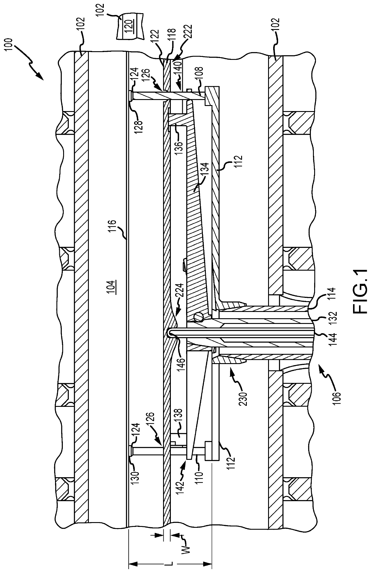
[0018]Turning now to FIG. 1, a reactor 100 in accordance with at least one embodiment of the disclosure is illustrated. Reactor 100 includes a reaction chamber 102 including a reacti...


PUM

PropertyMeasurementUnit
distanceaaaaaaaaaa
lengthaaaaaaaaaa
distanceaaaaaaaaaa

Abstract

A substrate support assembly suitable for use in a reactor including a common processing and substrate transfer region is disclosed. The substrate support assembly includes a susceptor and one or more lift pins that can be used to lower a substrate onto a surface of the susceptor and raise the substrate from the surface, to allow transfer of the substrate from the processing region, without raising or lowering the susceptor.

Description

FIELD OF INVENTION[0001]The disclosure generally relates to apparatus for gas-phase processes. More particularly, exemplary embodiments of the present disclosure relate to a reactor including a common substrate transfer and processing region and to a substrate lift mechanism suitable for use therein.BACKGROUND OF THE DISCLOSURE[0002]Gas-phase reactors for processing substrates, such as semiconductor wafers, often include a susceptor within a reaction chamber. During processing, one or more substrates are placed within the reaction chamber and onto the susceptor using a robotic arm. After processing, the substrate(s) are removed from the surface of the susceptor and through an opening in the reaction chamber using the robotic arm.[0003]Often, it is desirable to maintain a relatively small reaction space or region within the reaction chamber. The relatively small reaction space allows for more-efficient substrate processing. For example, a smaller amount of reactants can be used when ...

Claims


Application Information

Patent Timeline
Patent Type & Authority Patents(United States)
IPC IPC(8): H01L21/687H01L21/67C23C16/458C30B25/08C30B25/12
CPCH01L21/68742H01L21/68792C23C16/4584C23C16/4586C23C16/4581H01L21/67028C30B25/12H01L21/67248C30B25/08H01L21/67069H01L21/67126H01L21/68757H01J37/32715H01J37/32733H01J2237/332
Inventor HILL, ERICDISANTO, JOHN
Owner ASM IP HLDG BV
Why Eureka
Try Eureka