
Vascular lumen debulking catheters and methods

a technology of vascular lumen and catheter, which is applied in the field of percutaneous transluminal systems and methods for debulking body lumens, can solve the problems of reclosure or blockage of body lumen, myocardial infarction, and many currently available side-cutting atherectomy catheters have difficulty in capturing occluding material in the cutting aperture, so as to facilitate the removal of material, improve material and shape, and enhance the removal of occlusive material

Inactive Publication Date: 2011-04-19
TYCO HEALTHCARE GRP LP
View PDF166 Cites 143 Cited by
  • Summary
  • Abstract
  • Description
  • Claims
  • Application Information

AI Technical Summary

Benefits of technology

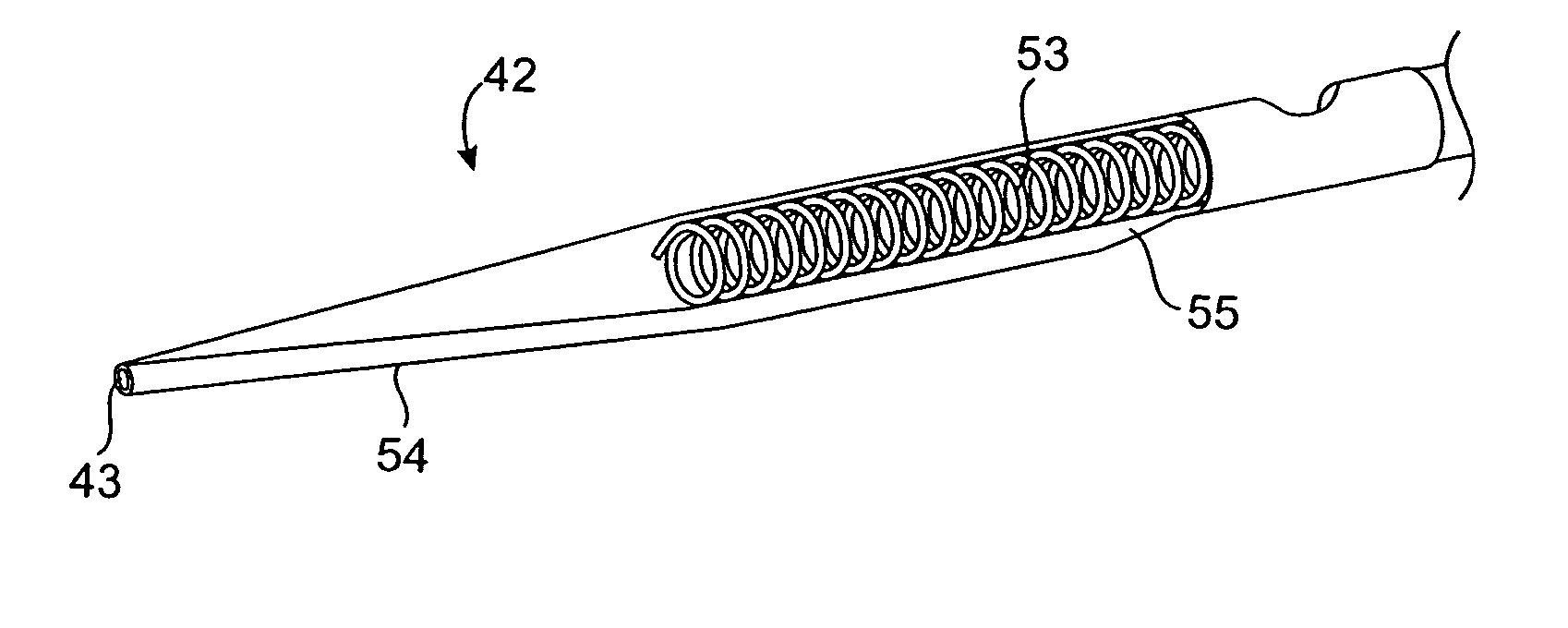
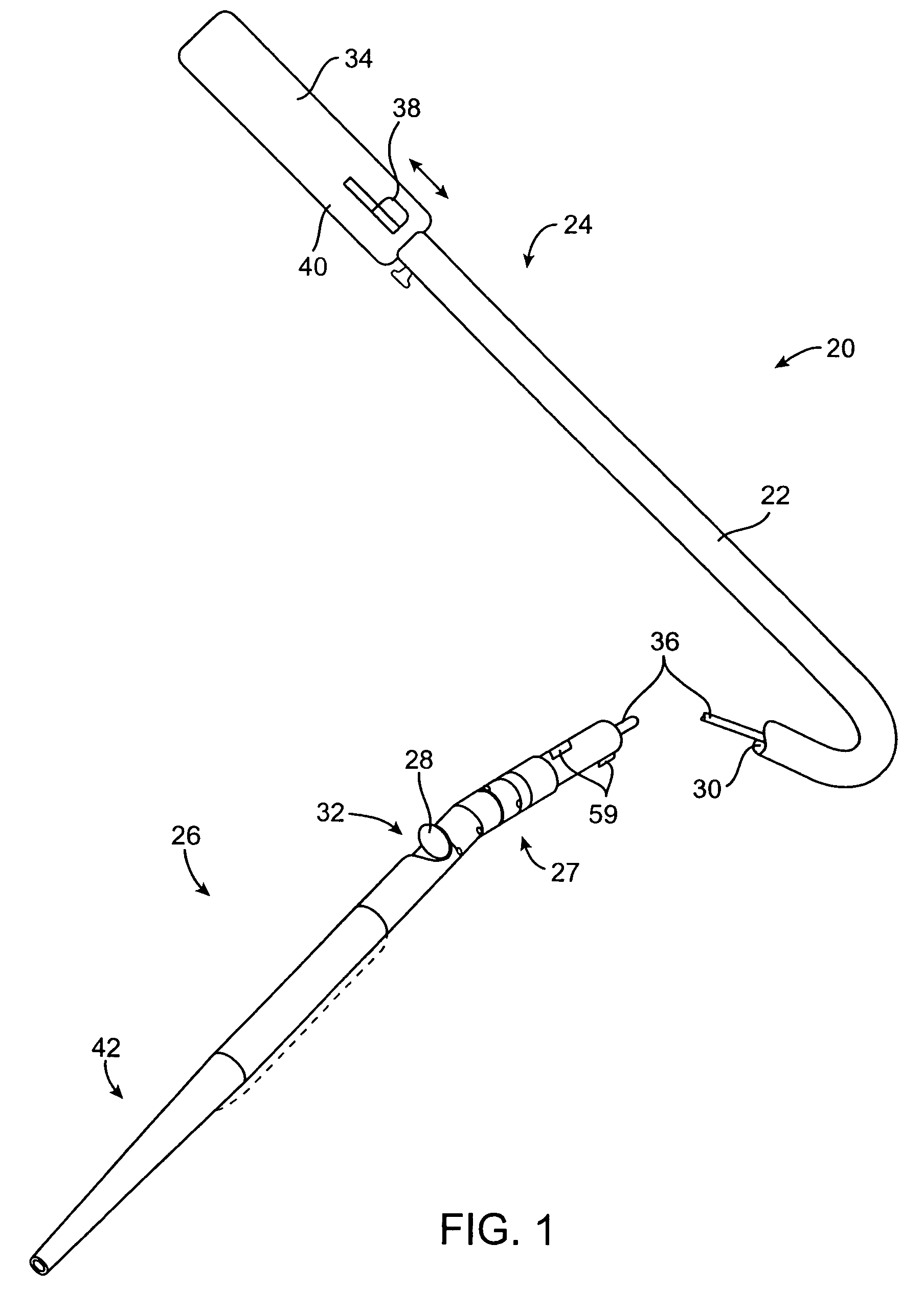
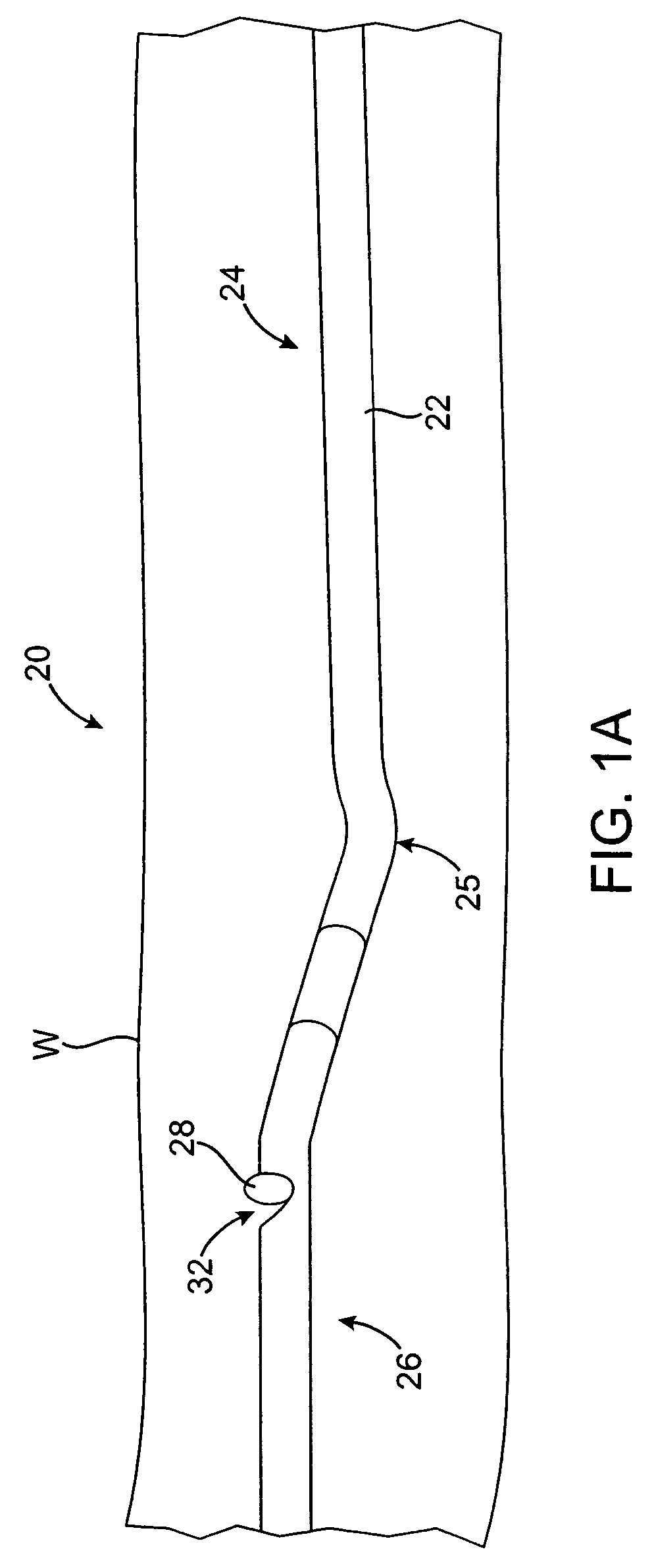
[0011]Catheters of the present invention are configured to enhance the removal of occlusive material from a body lumen by providing catheters with one or more improved features. For example, some embodiments include a deflected or deflectable portion of the catheter, such as a distal portion that is deflectable relative to the proximal portion or a deflected or deflectable section near the distal end of the proximal portion. Such deflection may help to urge a portion of the catheter into contact with material adhered to the sidewall of a body lumen to facilitate removal of the material. Deflection may also expose the tissue debulking assembly through the window on the catheter body. In various embodiments, other advantageous features of the catheters of the present invention include, but are not limited to, telescoping guidewire lumens, a shuttle mechanism for locking the tissue debulking assembly in a given position, debulking assemblies having improved materials and shapes, imaging devices, improved material storage tips and the like.
[0012]In one aspect of the present invention, a debulking catheter for removing material from a body lumen includes a catheter body and a tissue debulking assembly. The catheter body generally includes a proximal portion and a distal portion, with the distal portion having a window. The tissue debulking assembly is disposed at least partially within the distal portion of the catheter body and is radially movable to expose at least a portion of the assembly through the window to contact the material in the body lumen. The tissue debulking assembly itself may take any of a number of suitable forms, but in one embodiment it comprises a rotatable cutter. Optionally, such a cutter may include a beveled edge for contacting the material in the body lumen while preventing injury to the body lumen. In some embodiments, the cutter includes a tungsten carbide cutting edge for improved durability and cutting ability. In still other embodiments, the tissue debulking assembly may comprise a radio frequency electrode, a laser, an ultrasound emitter and / or the like.

Problems solved by technology

Atheromatous and other vascular deposits restrict blood flow and can cause ischemia which, in acute cases, can result in myocardial infarction.
One factor impeding the success of stent technology in endoluminal treatments is the frequent occurrence of in-stent restenosis, characterized by proliferation and migration of smooth muscle cells within and / or adjacent to the implanted stent, causing reclosure or blockage of the body lumen.
For example, many currently available side-cutting atherectomy catheters have difficulty in capturing occluding material in the cutting aperture.
Since most cutter housings are rigid, such lengthening makes it more difficult to introduce the distal end of the catheter through tortuous regions of the vasculature.
Such balloons, however, unduly increase the size of the distal portion of the catheter.
Even with the balloon, the amount of material that can be removed by conventional atherectomy catheters is limited by the size of the cutting window.
Other disadvantages of some catheters include cutting elements with less than ideal hardness, inadequate storage space within the catheter for containing removed material, sub-optimal guide wire lumens, and / or the like.
In addition, the available atherectomy catheters generally provide material insufficient in quantity and / or quality for testing by many histological, array, proteomic or other biochemical or molecular methods.
This amount of material is not typically enough to carry out more than one test, or is insufficient to successfully carry out a number of diagnostic tests available to the physician or researcher.

Method used


Image

  • Vascular lumen debulking catheters and methods
  • Vascular lumen debulking catheters and methods
  • Vascular lumen debulking catheters and methods

Examples


example 1

Bilateral Appendage Comparison of Protein Content in Resected Arterial Plaque

[0133]For this study five patients with peripheral arteriolosclerosis were selected. Plaque tissue was removed from both legs in all patients. Some of the removed tissue was frozen. For analysis some of the frozen tissue was thawed and fixed with 10% formalin and subjected to routine paraffin processing. Five micron sections were cut, stained with elastic and Trichrome collagen stains and these slides were microscopically evaluated for general histology. Only the one patient (BAKCA) had some discordance between the stained protein content, the rest of the patients had the same lipid and protein levels as measured by immunohistochemistry in both their left and right legs. Gene array information was yielded from testing the material in the right and left legs of the patients.

example 2

[0134]Tissue extraction and preparation is conducted as described in Example 1. The isolated tissue is analyzed for the following protein markers using standard techniques known in the art: interleukin-18, RANTES, fractalkine, interleukin-1-beta, matrix metalloproteinase-9, tumor necrosis factor-alpha, monocyte inflammatory protein alpha, E-selectin and P-selectin.


PUM


Abstract

A debulking catheter comprising a tissue debulking assembly for removing a continuous strand of material from a body lumen. Catheters of the present invention generally include a catheter body having proximal and distal portions and a tissue debulking assembly disposed at least partially within the distal portion. The tissue debulking assembly is radially movable to expose at least a portion of the assembly through a window on the catheter body. The catheter is advanced transluminally through the body lumen to contact material in the body lumen and remove a plane of continuous material that has a length that is typically longer than a length of the window on the catheter. The continuous material may be directed into a collection chamber. Thereafter, the material may be removed from the collection chamber and preserved or tested.

Description

CROSS-REFERENCES TO RELATED APPLICATIONS[0001]The present application is a continuation-in-part of U.S. patent application Ser. No. 11 / 108,887 filed Apr. 19, 2005, which is a continuation in part of U.S. patent application Ser. No. 10 / 896,741, filed Jul. 21, 2004, which is a continuation-in-part of U.S. patent application Ser. No. 10 / 288,559, filed Nov. 4, 2002, which is a continuation-in-part of U.S. patent application Ser. No. 10 / 027,418, filed Dec. 19, 2001, which claims the benefit of Provisional Patent Application Ser. No. 60 / 257,704, filed Dec. 20, 2000, and Provisional Patent Application Ser. No. 60 / 272,273 filed Feb. 27, 2001, the complete disclosures of which are incorporated herein by reference.[0002]Application Ser. No. 10 / 896,741 also claims the benefit of Provisional Application No. 60 / 381,632, filed on May 19, 2002, the complete disclosure of which is incorporated herein by reference. The present application is also related to U.S. patent application Ser. No. 09 / 377,88...

Claims


Application Information

Patent Timeline
Patent Type & Authority Patents(United States)
IPC IPC(8): A01N1/00A61K35/12
CPCA61B10/02A61B10/0266A61B10/04G06F19/322A61B17/320783A61K35/12A61B17/320758A61B10/0096A61B17/320725A61B19/44A61B2017/00778A61B2017/320791A61B90/90G16H10/60
Inventor SIMPSON, JOHN B.
Owner TYCO HEALTHCARE GRP LP
Learn More