Removable essentially cylindrical implants

a technology essentially cylindrical parts, which is applied in the field of essentially cylindrical implants, to achieve the effect of little complication

Inactive Publication Date: 2007-08-07
MERIT MEDICAL SYST INC
View PDF416 Cites 127 Cited by
  • Summary
  • Abstract
  • Description
  • Claims
  • Application Information

AI Technical Summary

Benefits of technology

[0004]There is thus a need to so configure cylindrical implants of this type as to allow a removal from the body in a simple manner with as little complication as possible.

Problems solved by technology

In many cases, this causes problems as newly formed tissue grows to and—depending on the structure—also through the implants so that the removal may cause complications.

Method used


Image

  • Removable essentially cylindrical implants
  • Removable essentially cylindrical implants
  • Removable essentially cylindrical implants

Examples


Embodiment Construction

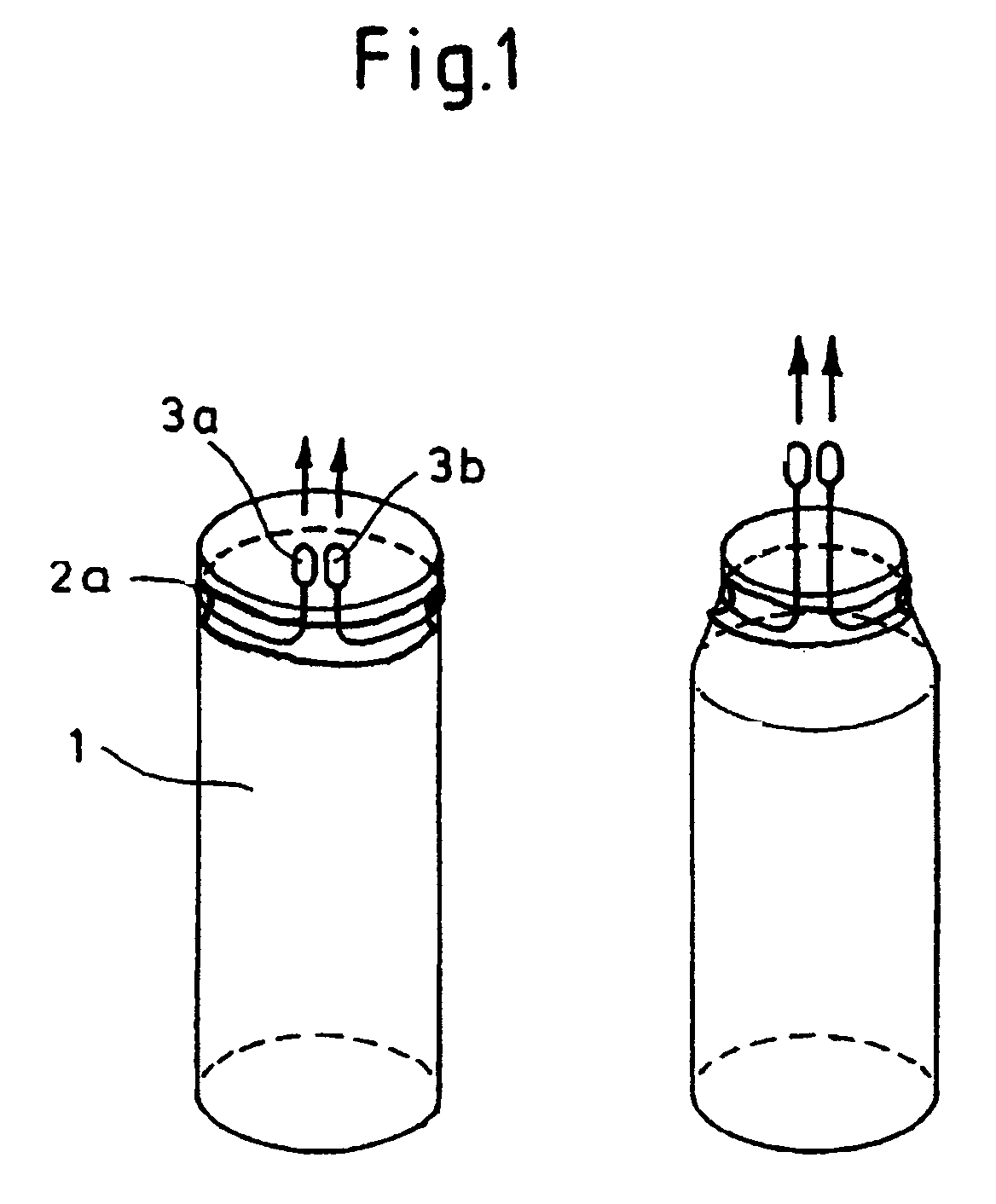
[0018]The implant 1 of substantially cylindrical shape is wrapped either on one end with a wire-shaped single loop which may be secured either to the outer wall of the implant or is wrapped several times about the implant. This wire-shaped loop 2a has on each end a catch device 3a and 3b, respectively, which cause at least partially a reduction in diameter of the implant when being pulled in direction of the indicated arrows.

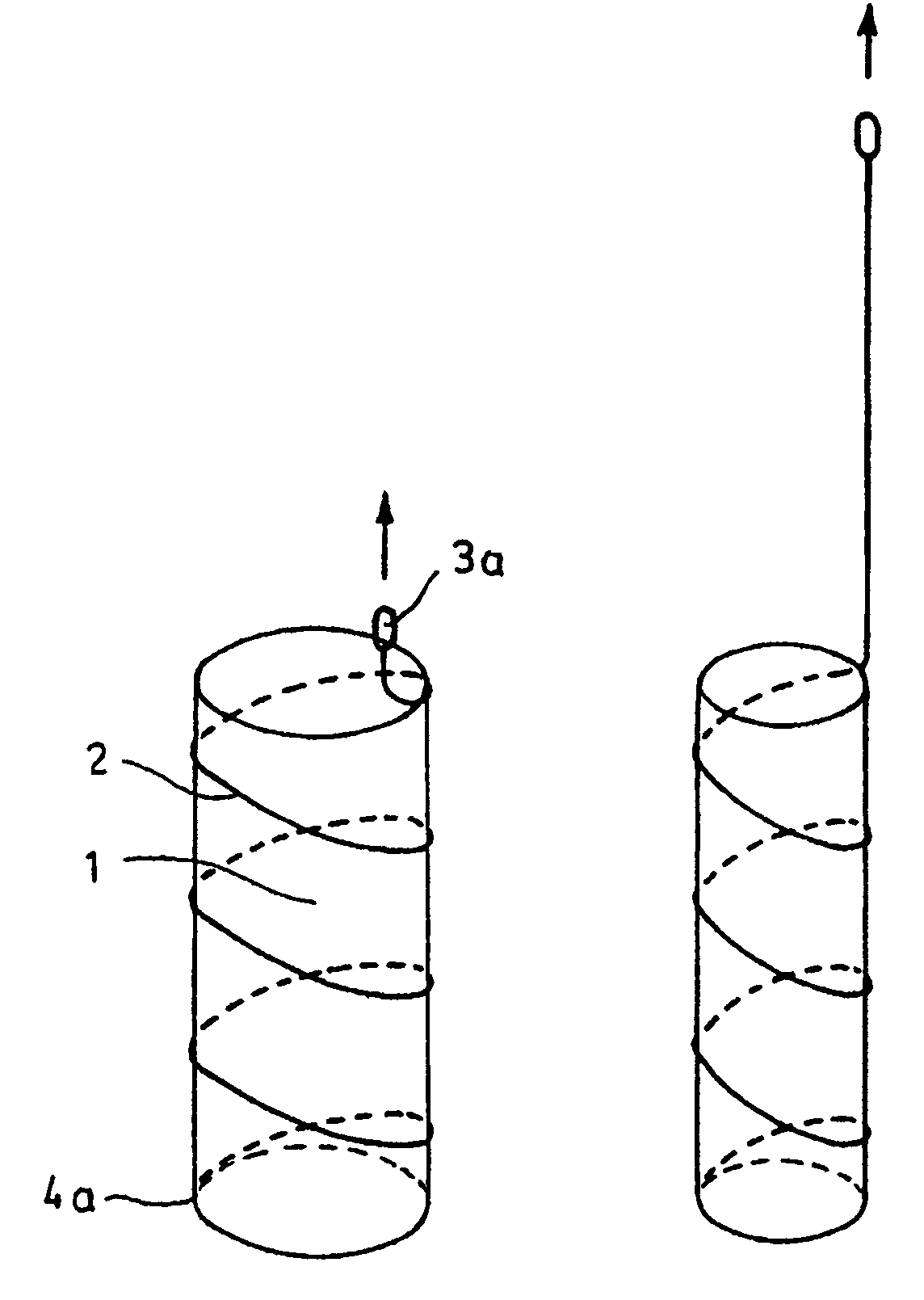
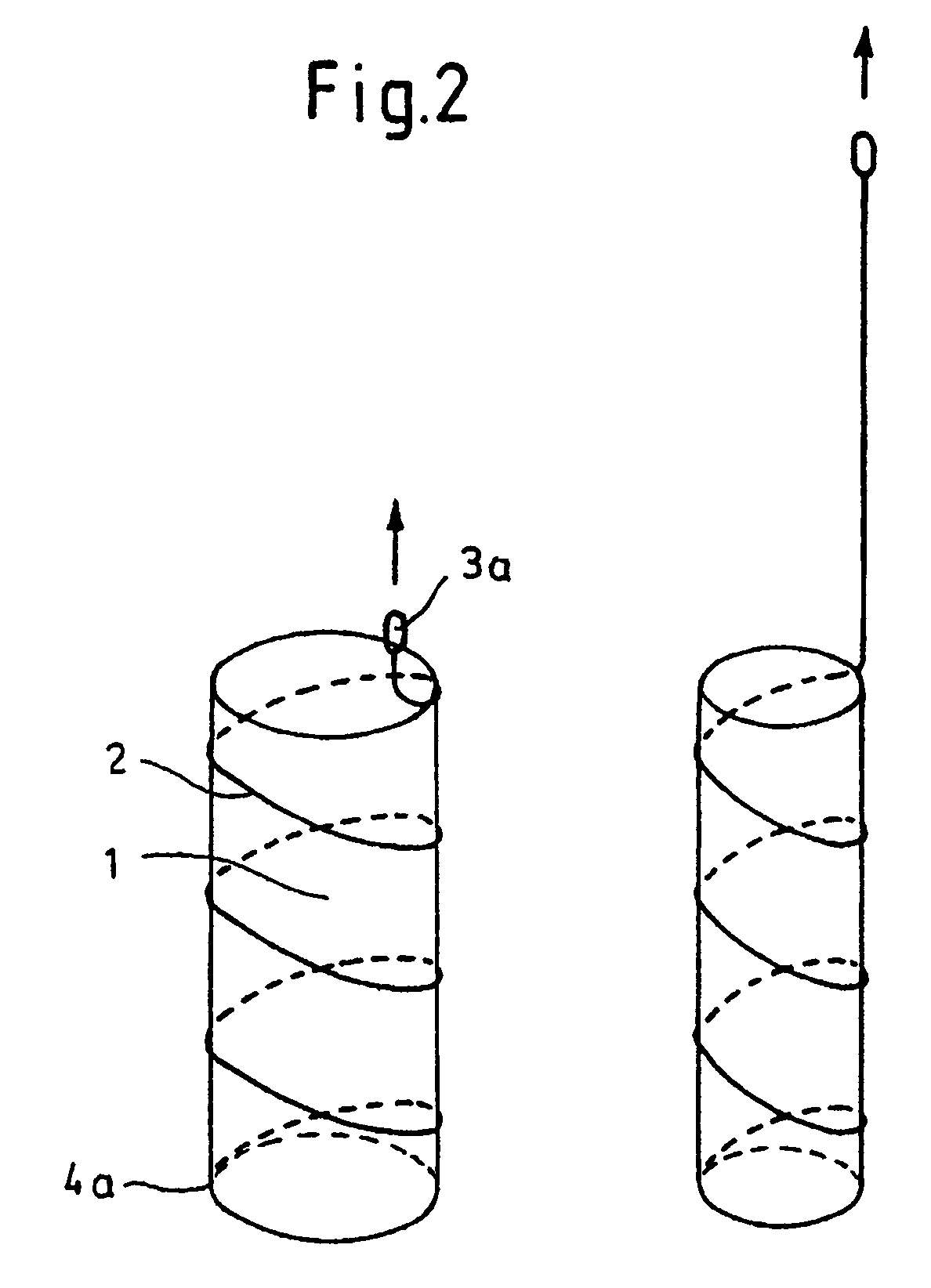
[0019]Instead of a single loop, the wire may also be configured as helical loop 2, as shown in FIG. 2, which includes a catch device 3a and is secured to the end 4a of the implant such that a reduction in the overall diameter of the implant is realized when pulling in the indicated arrow direction.

[0020]As shown in FIG. 3, it is also possible to combine a helical loop and a single loop with one another, by providing the implant 1, on one hand, with a helical loop 2a which is secured on the end 4a, and on the other hand, with a single loop 2b, whereby both loops ...


PUM


Abstract

The invention relates to removable, essentially cylindrical implants which are characterized in that they can be reduced in diameter and are wrapped once or several times at one or more levels by one or more elastic, thin wire-shaped structure(s) (2a, 2b) which include(s) a catch device (3a, 3b) at least on one end thereof.

Description

CROSS REFERENCE TO RELATED APPLICATIONS[0001]The present application is a National Stage of International Application No. PCT / DE02 / 01244 filed Apr. 5, 2002, which claims priority from German Patent No. DE 10118944 filed Apr. 18, 2001, the contents of which are incorporated herein by reference.BACKGROUND OF THE INVENTION[0002]The invention relates to removable, essentially cylindrical implants.[0003]Occasionally, for various reasons, such implants, i.e. predominantly so-called stents, must be removed from the body after the surgical procedure. In many cases, this causes problems as newly formed tissue grows to and—depending on the structure—also through the implants so that the removal may cause complications.SUMMARY OF THE INVENTION[0004]There is thus a need to so configure cylindrical implants of this type as to allow a removal from the body in a simple manner with as little complication as possible.[0005]Surprisingly, it has been found that the difficulties experienced heretofore ...

Claims


Application Information

Patent Timeline
Patent Type & Authority Patents(United States)
IPC IPC(8): A61F2/06A61F11/00A61B17/22A61F2/88A61F2/95
CPCA61F2/88A61F2/95A61B17/221A61B2017/2215A61F2220/0058A61F2002/9511A61F2002/9528A61F2220/0025
Inventor FREITAG, LUTZ
Owner MERIT MEDICAL SYST INC
Why Eureka
Try Eureka