Turbine blade/vane

Active Publication Date: 2005-06-14
SIEMENS AG
View PDF15 Cites 18 Cited by
  • Summary
  • Abstract
  • Description
  • Claims
  • Application Information

AI Technical Summary

Benefits of technology

[0025]Advantages achieved by various embodiments of the invention include, in particular, the fact that due to the provision of an incident flow duct and an efflux duct in the turbine blade/vane, the cooling medium can be conducted along the inside of the turbine blade/vane in a transverse direction during transfer from the incident flow duct into the efflux duct so that an area exposure of the blade/vane aerofoil is made possible and particula

Problems solved by technology

In this way, unavoidable flow

Method used


Image

  • Turbine blade/vane
  • Turbine blade/vane
  • Turbine blade/vane

Examples


Embodiment Construction

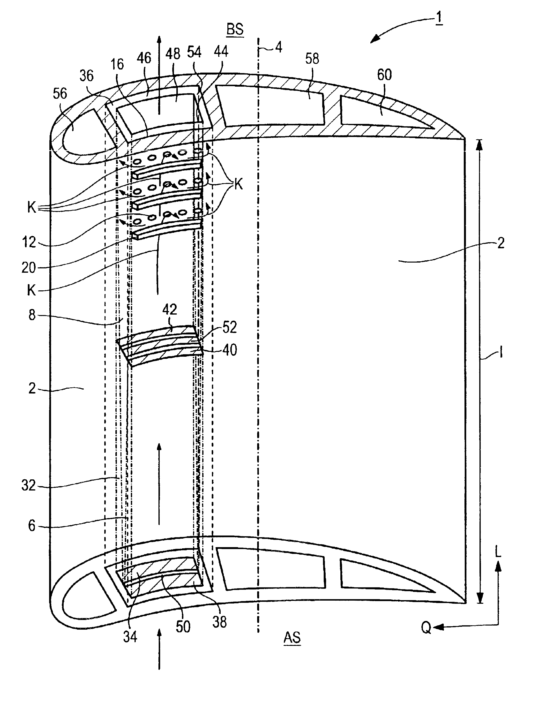
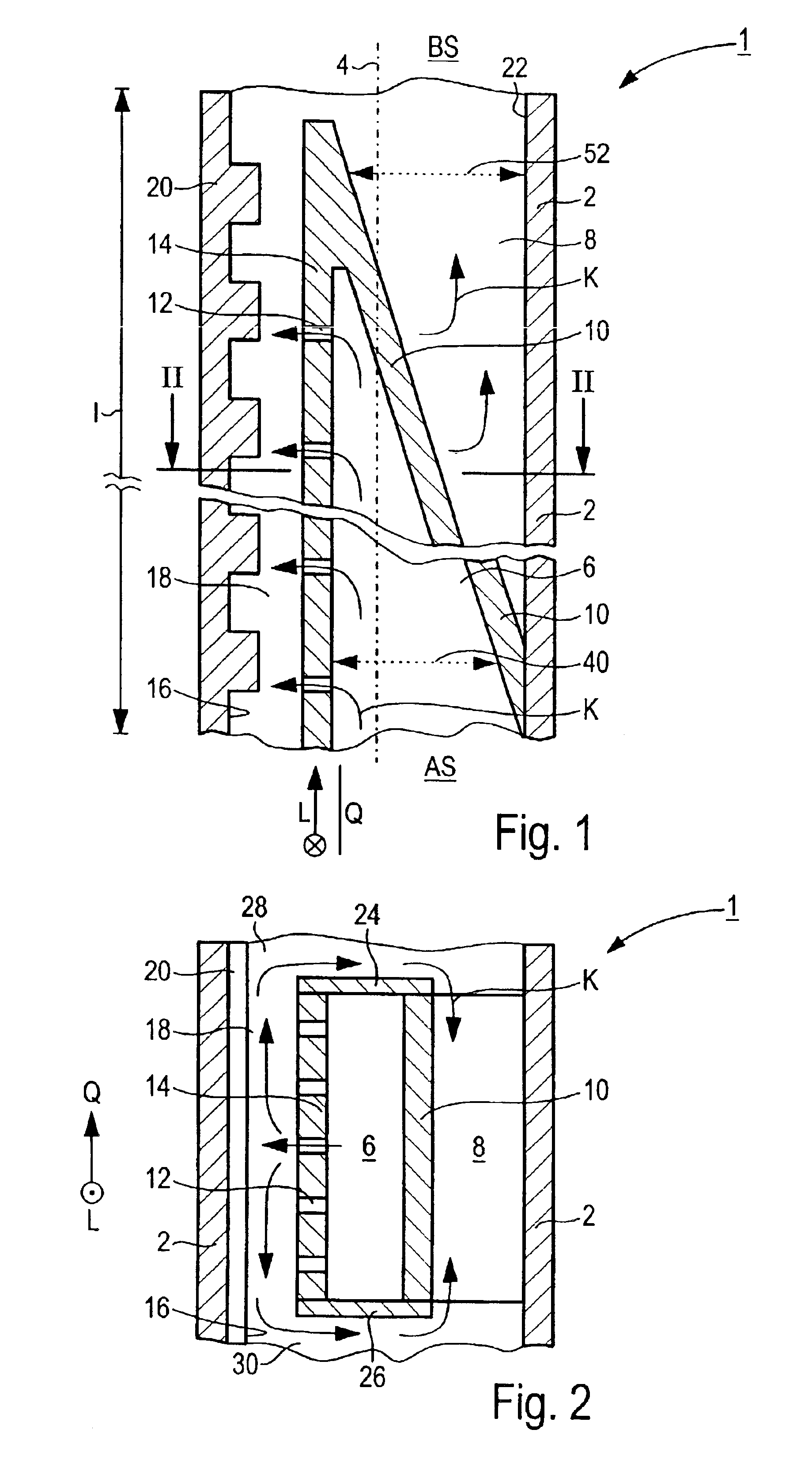
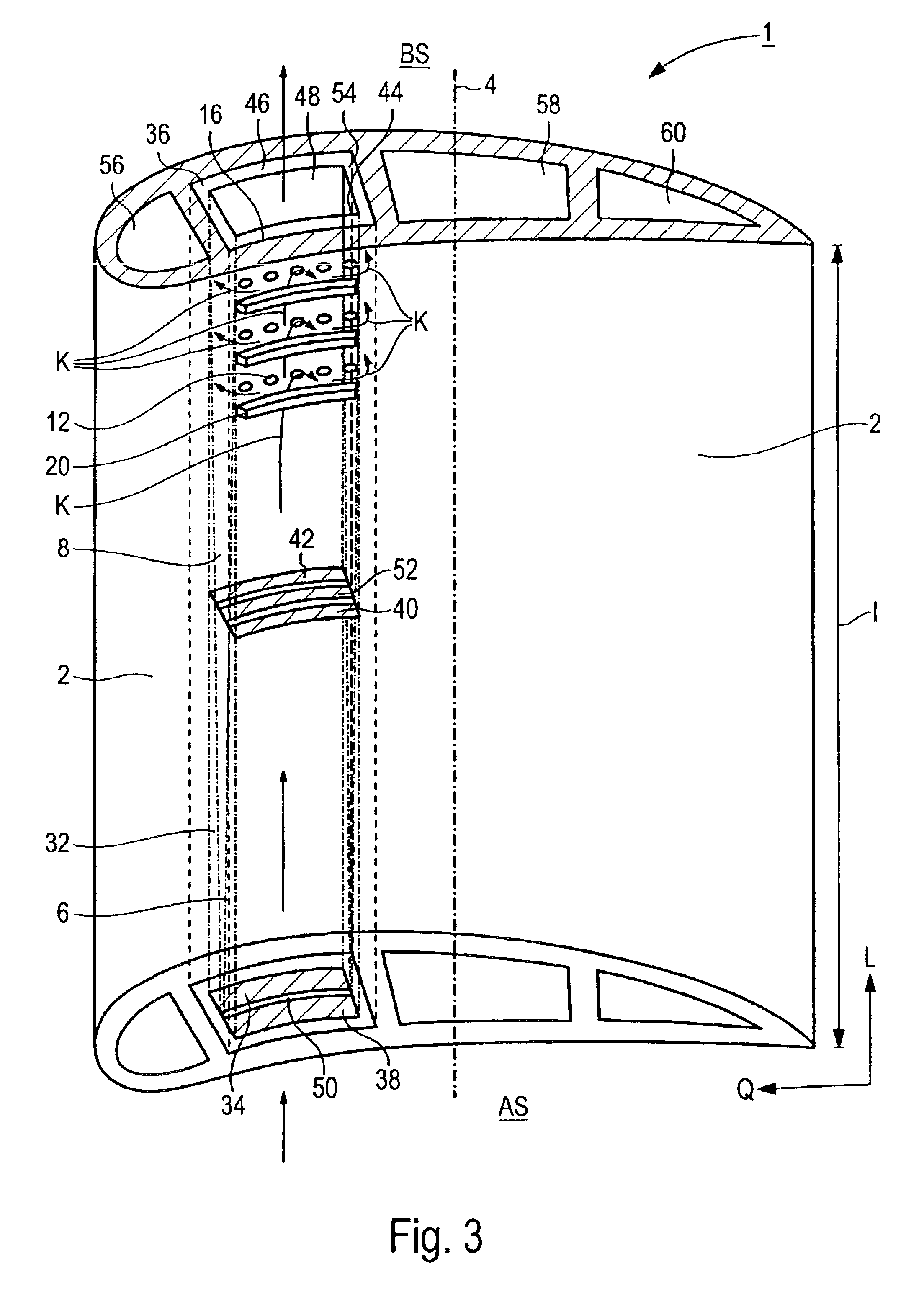
[0032]The turbine blade / vane shown in FIG. 1 has a blade / vane aerofoil 2 which extends along a blade / vane axis 4. In order to appropriately influence a working medium flowing in an associated turbine unit, the blade / vane aerofoil 2 is domed and / or curved.

[0033]The turbine blade / vane 1 is configured as a guide vane for a gas turbine (not shown here in any more detail) and is configured, in the manner of a closed cooling system, as a turbine blade / vane which can be cooled using cooling air as the cooling medium. For this purpose, cooling medium K can flow through the blade / vane aerofoil 2, principally in its longitudinal direction L, the cooling medium K entering into the blade / vane aerofoil 2 from a cooling medium incident flow end AS and emerging again from the blade / vane aerofoil at a cooling medium efflux end BS.

[0034]An incident flow duct 6, into which cooling medium K can enter from the cooling medium incident flow end AS, and an efflux duct 8 for cooling medium K are routed wit...


PUM


Abstract

A turbine blade/vane, having a blade/vane aerofoil which extends along a blade/vane axis and through which cooling medium flows, mainly in the longitudinal direction of the turbine blade/vane, is configured comparatively simply for reliable and effective closed cooling. In particular, it is configured with the use of cooling air as the cooling medium. An incident flow duct and an efflux duct for cooling medium are routed within the blade/vane aerofoil, essentially over its complete length. The incident flow duct and the efflux duct are connected together on the cooling medium side in such a way that cooling medium passing from the incident flow duct into the efflux duct is conducted in a transverse direction along a wall inner surface, which has to be cooled, of the blade/vane aerofoil.

Description

[0001]The present application hereby claims priority under 35 U.S.C. §119 on European patent application number 01119263.0 filed Aug. 9, 2001, the entire contents of which are hereby incorporated by reference.FIELD OF THE INVENTION[0002]The invention generally relates to a turbine blade / vane. Preferably, it relates to one having a blade / vane aerofoil which extends along a blade / vane axis and through which cooling medium can flow, mainly in the longitudinal direction of the turbine blade / vane.BACKGROUND OF THE INVENTION[0003]Gas turbines are employed in many fields for driving generators or machinery. In this process, the energy content of a fuel is used to generate a rotational motion of a turbine shaft. For this purpose, the fuel is burnt in a combustion chamber, with compressed air being supplied from a air compressor. The working medium at high pressure and at high temperature generated by the combustion of the fuel in the combustion chamber is conducted, in this process, via a t...

Claims


Application Information

Patent Timeline
IPC IPC(8): F01D5/18F01D9/02
CPCF01D5/189F05D2260/205F05D2260/201
Inventor TIEMANN, PETER
Owner SIEMENS AG
Why Eureka
Try Eureka