
Device for detecting moisture, for use with an arrangement for monitoring an access to a patient

Active Publication Date: 2013-06-13
FRESENIUS MEDICAL CARE DEUTSCHLAND GMBH
View PDF1 Cites 31 Cited by
  • Summary
  • Abstract
  • Description
  • Claims
  • Application Information

AI Technical Summary

Benefits of technology

The present invention provides an arrangement for monitoring access to a patient, particularly for extracorporeal blood treatment, that is cost-effective and easy to use. The arrangement is reliable, flexible, and highly biocompatible. The technical effects of this invention are improved monitoring of patient access during extracorporeal blood treatment, which can contribute to better treatment outcomes and reduced complications. This invention can be used in an apparatus for extracorporeal blood treatment.

Problems solved by technology

Despite the vascular access being monitored regularly by the hospital staff there is, basically, a risk of the puncturing needle slipping out of the patient's blood vessel unnoticed.
The risk of the puncturing needle slipping out unnoticed also exists with home dialysis.
Whereas the printed conductors can be printed on the substrate material with relatively little production-related cost or complication, the production of a printed terminating resistor having a defined resistance which is to be within relatively tight tolerances is found to be relatively problematic.
On the other hand it has been seen that the alternating bending strength of terminating resistors printed on a substrate material may be relatively low.
This is a problem inasmuch as the terminating resistor is constantly stressed in bending when there are movements on the part of the patient.
A further disadvantage of this design lies in the fact that a small drop of liquid situated on the terminating resistor itself cannot be detected.
Even though lower tolerances can be achieved for the terminating resistor with the alternative design, there are found to be problems in practice in obtaining a repeatable terminating resistor which is printed on the substrate material.
A further disadvantage of printed terminating resistors lies in the fact that sweat from the patient may reduce the value of the resistance of the terminating resistor.
A further disadvantage of a printed terminating resistor arises from the requirement for a number of moisture sensors which is as large as possible to be arranged on a single printed sheet.
The size of the sheets for printing (sheets of nonwoven material) which can be inserted in the printing machine is limited due to the accuracy requirements imposed by the printing when, once the printed conductors printed with the silver-containing paste in the first printing operation have dried, the terminating resistors are to be printed in the graphite paste, in the second printing operation, on the same printed sheet in an exact position next to the printed conductors.
Because of the shrinkage of the sheet when the first printing dries, a non-uniform displacement occurs of the second printing relative to the first printing and this increases as the size of the sheets becomes larger and as from a certain sheet size can no longer be accepted because at least some of the terminating resistors are then no longer accurately positioned in the second printing operation.
However, for reasons of cost, an attempt has to be made to use sheets which are as large as possible carrying as many individual sensors as possible, because the specific costs of an individual sensor go down as the size of the printed sheet increases.
Also, the printing operation for applying the terminating resistors is dispensed with, thus saving production costs for the printing.
Leaks may occur if the connectors are not properly connected.
Crossing points of this kind cannot be avoided in printed circuits or can only be avoided at high cost.
However, the needle can then only be inserted once the covering has been applied.

Method used


Image

  • Device for detecting moisture, for use with an arrangement for monitoring an access to a patient
  • Device for detecting moisture, for use with an arrangement for monitoring an access to a patient
  • Device for detecting moisture, for use with an arrangement for monitoring an access to a patient

Examples


Embodiment Construction

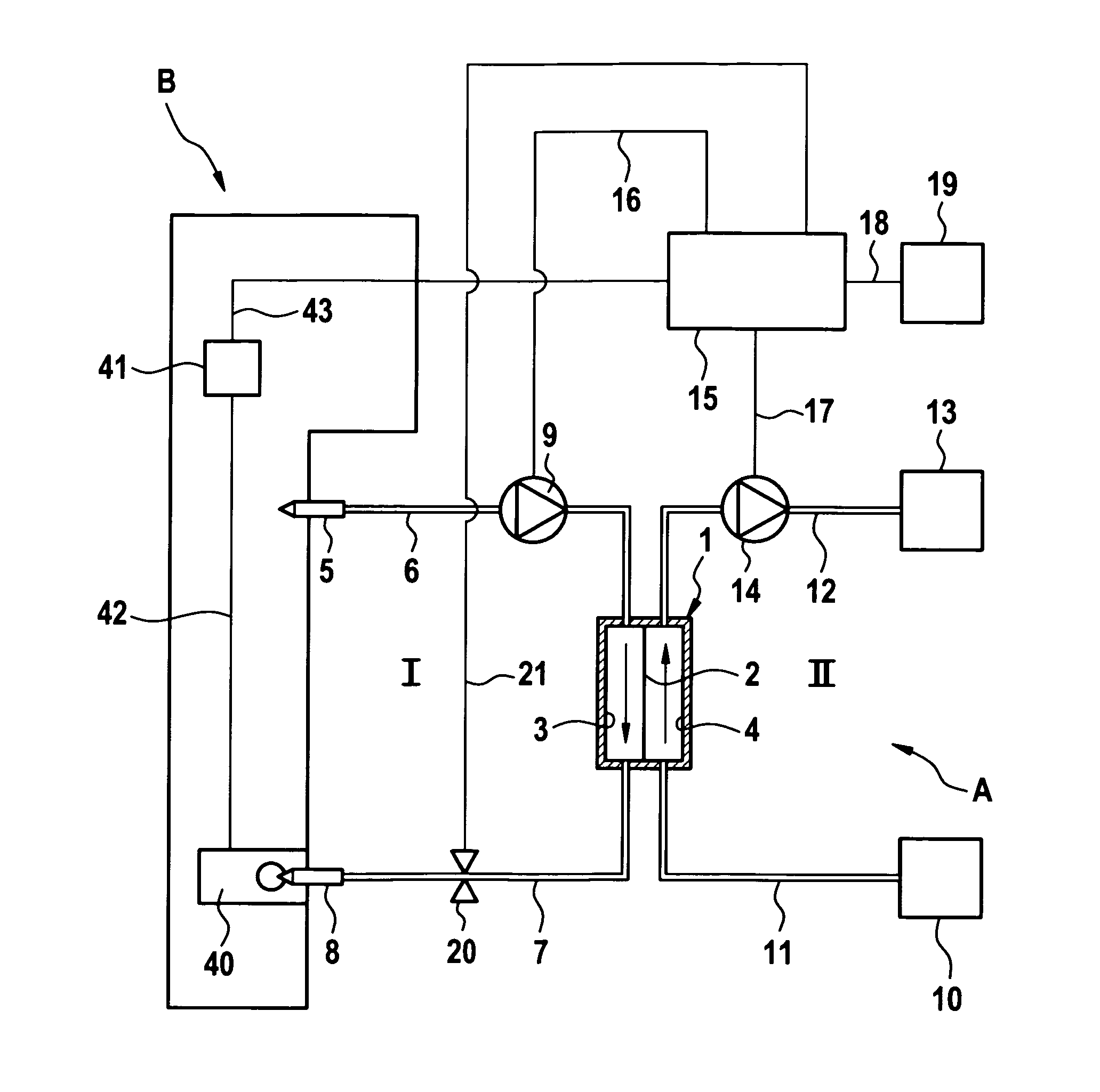
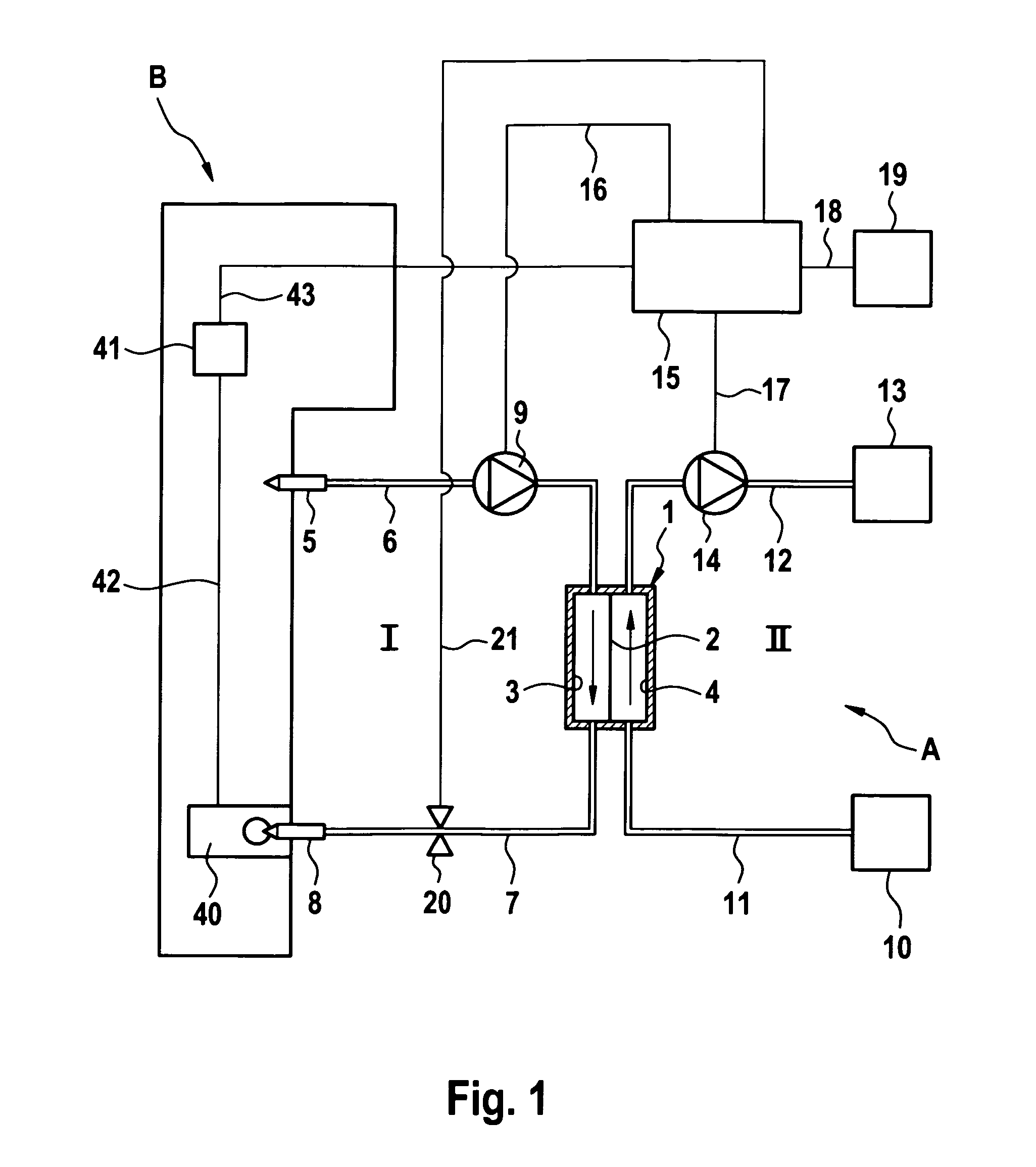
[0053]FIG. 1 shows the principal components of a blood-treating apparatus, and in particular a hemodialysis apparatus, A, which has an arrangement B for monitoring the arterial and venous vascular accesses. In the present embodiment, the monitoring arrangement B is part of the hemodialysis apparatus A. The dialysis apparatus will first be described by reference to FIG. 1.

[0054]The hemodialysis apparatus A has a dialyzer 1 which is divided by a semi-permeable membrane 2 into a blood chamber 3 and a dialysis-fluid chamber 4. Connected to the patient's fistula or shunt by means of an arterial puncturing needle 5 is a flexible arterial line 6 which runs to the inlet of the blood chamber 3 of the dialyzer. Leading away from the outlet of the blood chamber 3 of the dialyzer is a flexible venous line 7 which is connected to the patient's fistula or shunt by means of a venous puncturing needle 8. Connected into the flexible arterial line 6 is a blood pump 9 which pumps the blood in the extr...


PUM


Abstract

The present invention relates to a moisture detection system which takes the form of a covering to be applied to the patient's skin, and to a monitoring system for monitoring a vascular access for a blood-treating apparatus. The covering of the moisture detection system has a flexible substrate material to which an electrically conductive structure having printed conductors is applied as a moisture sensor. In accordance with one aspect of the present invention, because a terminating resistor is not part of a moisture detection system, the device can be inexpensively produced in large quantities. This is of advantage in that the moisture detection system is generally intended for once-only use. With the separate terminating resistor, there is no risk of the terminating resistor being damaged or its resistance changing due to movements on the part of the patient.

Description

CROSS REFERENCE TO RELATED APPLICATIONS[0001]This is a 371 national phase application of PCT / EP2011 / 003044 filed Jun. 21, 2011, which claims priority from German Patent Application No. DE 10 2010 024 654.9, filed Jun. 22, 2010.FIELD OF INVENTION[0002]The present invention relates to a device for detecting moisture, for use with an arrangement for monitoring an access to a patient for an apparatus by which, via a flexible line, a liquid is fed to a patient and / or a liquid is withdrawn from the patient, and in particular for monitoring the vascular access in an extracorporeal blood treatment in which a patient's blood is withdrawn from the patient via a flexible arterial line which has an arterial needle and is fed to the patient via a flexible venous line which has a venous puncturing needle. As well as this, the present invention also relates to an arrangement for monitoring an access to a patient which has a device for detecting moisture. What is more, the present invention also re...

Claims


Application Information

Patent Timeline
IPC IPC(8): A61M5/50A61M1/30
CPCA61M1/3653A61M2205/15A61M1/3656A61M5/5086A61M1/30
Inventor HEPPE, JOHN
Owner FRESENIUS MEDICAL CARE DEUTSCHLAND GMBH
Learn More