Gas turbine and method for operating a gas turbine

a gas turbine and gas turbine technology, applied in the field of gas turbines, can solve the problems of inability to meet the actual gas turbine process of the gas turbine, inability to supply cooling air to and loss of cooling air flowing into the cooling air supply system in terms of the actual gas turbine process for the generation of mechanical energy, etc., to achieve low complication, high specific power, and high efficiency

Inactive Publication Date: 2005-01-11
SIEMENS AG
View PDF16 Cites 19 Cited by
  • Summary
  • Abstract
  • Description
  • Claims
  • Application Information

AI Technical Summary

Benefits of technology

An object of an embodiment of the invention is to provide a gas turbine in which, with comparatively little complication, a particularly high efficiency, a high specific power and particularly low emissions of oxides of nitrogen are achieved. A further object of an embodiment of the invention is to provide a corresponding method for operating a gas turbine.
In conventional technology, the cooling air flowing into the cooling air supply system is lost in terms of the actual gas turbine process for the generation of mechanical energy because it is only used for the cooling of highly stressed components and does not participate in the combustion process. The admixture of fuel to the cooling air makes it possible to permit the combustion of the cooling air flow, which is mixed with fuel, after cooling has taken place in the hot gas region of the gas turbine. By this, work is also performed by the cooling air flow and the efficiency of the gas turbine increases. At the same time, however, the ISO temperature of the gas turbine does not increase when, for example, using the cooling air flow for cooling a gas turbine blade / vane. The ISO temperature is the hypothetical, computational turbine inlet temperature of a cooled gas turbine. It is smaller than the combustion temperature which is present in the primary zone of the combustion chamber. The difference between the combustion temperature and ISO temperature increases with the cooling air quantity which, in turn, increases with the ISO temperature. Typical ISO temperatures of large stationary gas turbines are located at about 1200° C., whereas the combustion temperatures are located at approximately 1400° C. A high efficiency and a high specific power of the gas turbine demands the smallest possible difference between combustion temperature and ISO temperature. There is, therefore, a great incentive to increase the ISO temperature at a given combustion temperature or to reduce the combustion temperature at a given ISO temperature.
A second possibility for reducing the ratio between fuel quantity and combustion air quantity is to reduce the fuel quantity burnt in the combustion chamber. Because the fuel quantity is dictated by the power to be operated, this is only possible if some of the fuel is transferred from the combustion air flow flowing into the combustion chamber to other suitable additional combustion air flows and is burnt, not in the combustion chamber but thermodynamically favorably at a high temperature level—if possible before the expansion in the turbine part. This is realized by an embodiment of the invention because the fuel is admixed before the cooling air flow is branched off and is burnt in the hot gas region of the gas turbine after the cooling of the hot gas component.
In contrast, very good mixing of fuel and combustion air is achieved by way of an embodiment of the invention because a large mixing section is achieved, without arranging additional mixers in the cooling air flow for this purpose. There is, therefore, no additional pressure loss.
This upstream supply of the essential part of the fuel supply compared with conventional embodiments means that the design of the gas turbine burners arranged in the combustion chamber is reduced, as it were, to producing an appropriate, canalized opening. The supply of fuel, therefore, no longer takes place in the burner but, where appropriate, substantially before the burner, viewed in the flow direction. This leads to an improved mixing of fuel and combustion air before entry into the combustion chamber. The burner is now essentially used for flame-holding by way, say, of a suitably designed swirl cascade. A pilot burner, which is used for the stabilization of a lean premixing combustion, can be additionally provided. However, an essentially smaller proportion of the fuel to be burnt in total is supplied to the pilot burner.

Problems solved by technology

This leads, at first glance, to an inappropriate flow of a fuel / combustion air mixture through the whole of the cooling air supply system.
In conventional technology, the cooling air flowing into the cooling air supply system is lost in terms of the actual gas turbine process for the generation of mechanical energy because it is only used for the cooling of highly stressed components and does not participate in the combustion process.

Method used


Image

  • Gas turbine and method for operating a gas turbine
  • Gas turbine and method for operating a gas turbine

Examples


Embodiment Construction

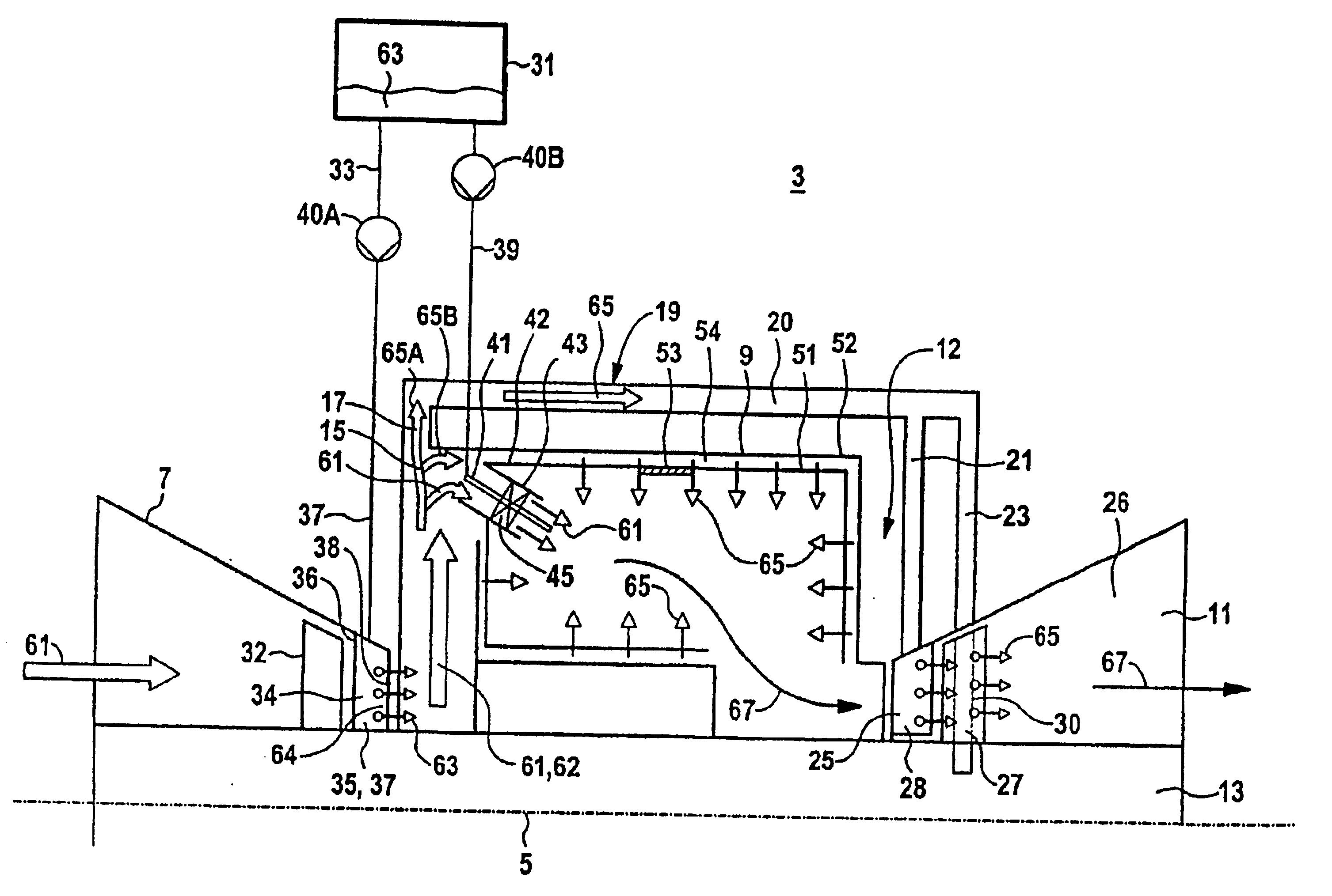
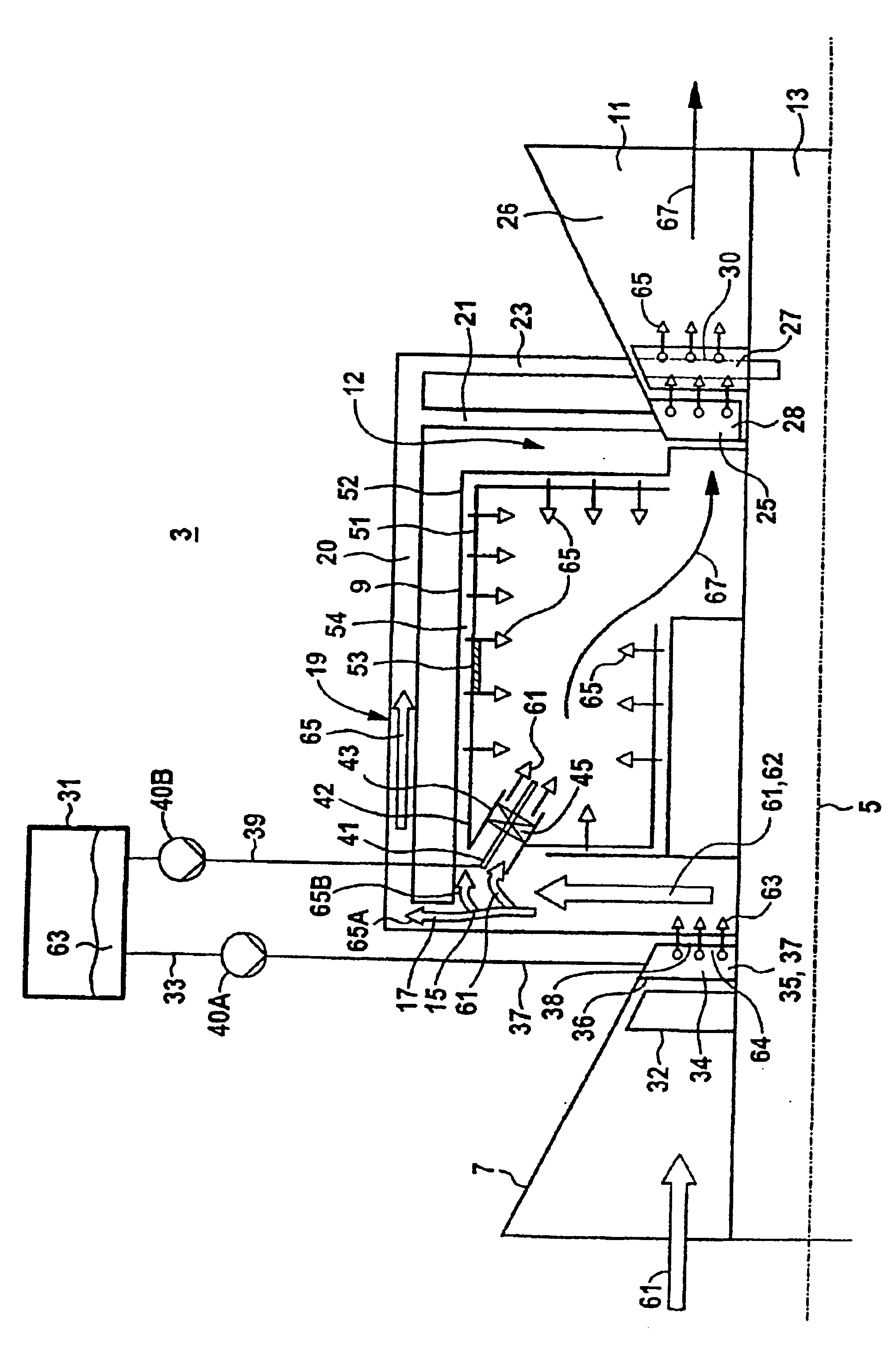
A compressor 7, a combustion chamber 9 and a turbine part 11 are arranged sequentially along an axis 5. The compressor 7 and the turbine part 11 are arranged on a common rotor 13. The compressor 7 is connected to the combustion chamber 9 by way of a combustion air duct 15. The combustion air duct 15 is connected to a cooling air supply system 19 at a branch position 17. The cooling air supply system 19 includes a first cooling air duct 20, from which a first secondary cooling air duct 21 and a second secondary cooling air duct 23 branch off.

The first secondary cooling air duct 21 is connected to a hollow guide vane 25 of a guide vane row 28 of the turbine part 11. The guide vane row 28 is a first guide vane row 28, viewed in the flow direction, of the turbine part 11. The second cooling air duct 23 is connected to a rotor blade 27 of a rotor blade row 30 of the turbine part 11. The rotor blade row 30 is a first rotor blade row 30, viewed in the flow direction, of the turbine part 11...


PUM


Abstract

The invention relates to a gas turbine (3) with reheat in the turbine section (11), whereby a fuel injection device (37) is provided for the injection of fuel (33) in to a combustion air flow (61) in the direction of flow before a cooling air flow (65) branching. By means of the early mixing of fuel (63) in the combustion air flow (61) and concomitant additional use of the cooling air flow (65) as combustion air, the specific output and the efficiency of the gas turbine (3) are improved.

Description

FIELD OF THE INVENTIONThe invention generally relates to a gas turbine having a compressor, a combustion chamber and a turbine part. It preferably relates to one having a cooling air supply system for branching off a cooling air flow from a combustion air flow and supplying this cooling air flow to a thermally stressed component. The invention also generally relates to a method for operating a gas turbine.BACKGROUND OF THE INVENTIONDE 43 30 613 A1 discloses a method and an appliance for operating a gas turbine. The gas turbine has a turbine part through which a driving gas flows, while expanding and delivering mechanical work. A fuel, which is burnt in the turbine part, is supplied to the driving gas. The fuel for combustion in the turbine part is admixed to a cooling air flow which is to be supplied to this turbine part. The proportion of the fuel in the cooling air flow is dimensioned in such a way that any self-ignition of the mixture is excluded.WO 97 / 29274 shows a method for ex...

Claims


Application Information

Patent Timeline
Patent Type & Authority Patents(United States)
IPC IPC(8): F02C3/22F02C7/22F02C3/20F02C6/00F23R3/30F02C7/236
CPCF02C3/22F02C7/22F02C6/003
Inventor ZIEGNER, MANFRED
Owner SIEMENS AG
Why Eureka
Try Eureka