Methods and apparatus for a combustion turbine nitrogen purge system

a technology of nitrogen purge and combustion turbine, which is applied in the direction of turbine/propulsion fuel valve, lighting and heating apparatus, machines/engines, etc., can solve the problems of carbon deposits, particulates obstructing the liquid fuel passage, and known existing combustion turbines with dual fuel capacity, etc., to achieve the effect of facilitating the removal of liquid fuel

Active Publication Date: 2010-06-08
GE INFRASTRUCTURE TECH INT LLC
View PDF17 Cites 130 Cited by
  • Summary
  • Abstract
  • Description
  • Claims
  • Application Information

AI Technical Summary

Benefits of technology

[0007]In one aspect, a method of operating a fuel system is provided. The method includes removing fuel from at least a portion of the fuel system using a gravity drain process The method also includes channeling nitrogen into at least a portion of the fuel system to facilitate removing air and residual fuel from at least a portion of the fuel system, thereby mitigating a formation of carbonaceous precipitate particulates. The method further includes removing air and nitrogen from at least a portion of the fuel system during a fuel refilling process using a venting process, such that at least a portion of the fuel system is substantially refilled with fuel and substantially evacuated of air and nitrogen. The method also includes removing air from at least a portion of the refilled fuel system using a venting process.
[0008]In another aspect, a nitrogen purge sub-system for a liquid fuel system for a dual fuel combustion turbine is provided. The fuel system has at least one cavity. The nitrogen purge sub-system includes a source of nitrogen coupled to a pipe in flow communication with the cavity. The purge sub-system further includes at least one valve that controls flow of nitrogen from the source to the cavity via the pipe. The at least one valve has an open condition such that nitrogen flows from the source through the pipe and into the cavity to facilitate removal of liquid fuel and air from the cavity such that a formation of a carbonaceous precipitate particulate is mitigated.
[0009]In a further aspect, a liquid fuel system including at least one valve, at least one pipe, at least one cavity, and at least one pump is provided. The at least one valve and at least one pipe include a nitrogen purge sub-system. The nitrogen purge sub-system includes a source of nitrogen coupled to a pipe in flow communication with the cavity. The purge sub-system further includes at least one valve that controls flow of nitrogen from the source to the cavity via the pipe. The at least one valve has an open condition such that nitrogen flows from the source through the pipe and into the cavity to facilitate removal of liquid fuel and air from the cavity such that a formation of a carbonaceous precipitate particulate is mitigated.

Problems solved by technology

Some known existing combustion turbines that have dual fuel capacity (gas fuel as primary and liquid fuel as backup) may be susceptible to carbon deposits, in the form of carbonaceous precipitate particulates, forming in the liquid fuel system.
If the carbonaceous particulate precipitation continues unabated, particulates may obstruct the liquid fuel passages.
In general, when liquid fuel systems remain out of service beyond a predetermined time limit, there is an increased likelihood that the static liquid fuel within the turbine compartment will begin to experience carbonaceous particulate precipitation.
As carbonaceous particulates form, they pose the potential of obstructing liquid fuel internal flow passages, including those in the combustion fuel nozzles.

Method used


Image

  • Methods and apparatus for a combustion turbine nitrogen purge system
  • Methods and apparatus for a combustion turbine nitrogen purge system
  • Methods and apparatus for a combustion turbine nitrogen purge system

Examples


Embodiment Construction

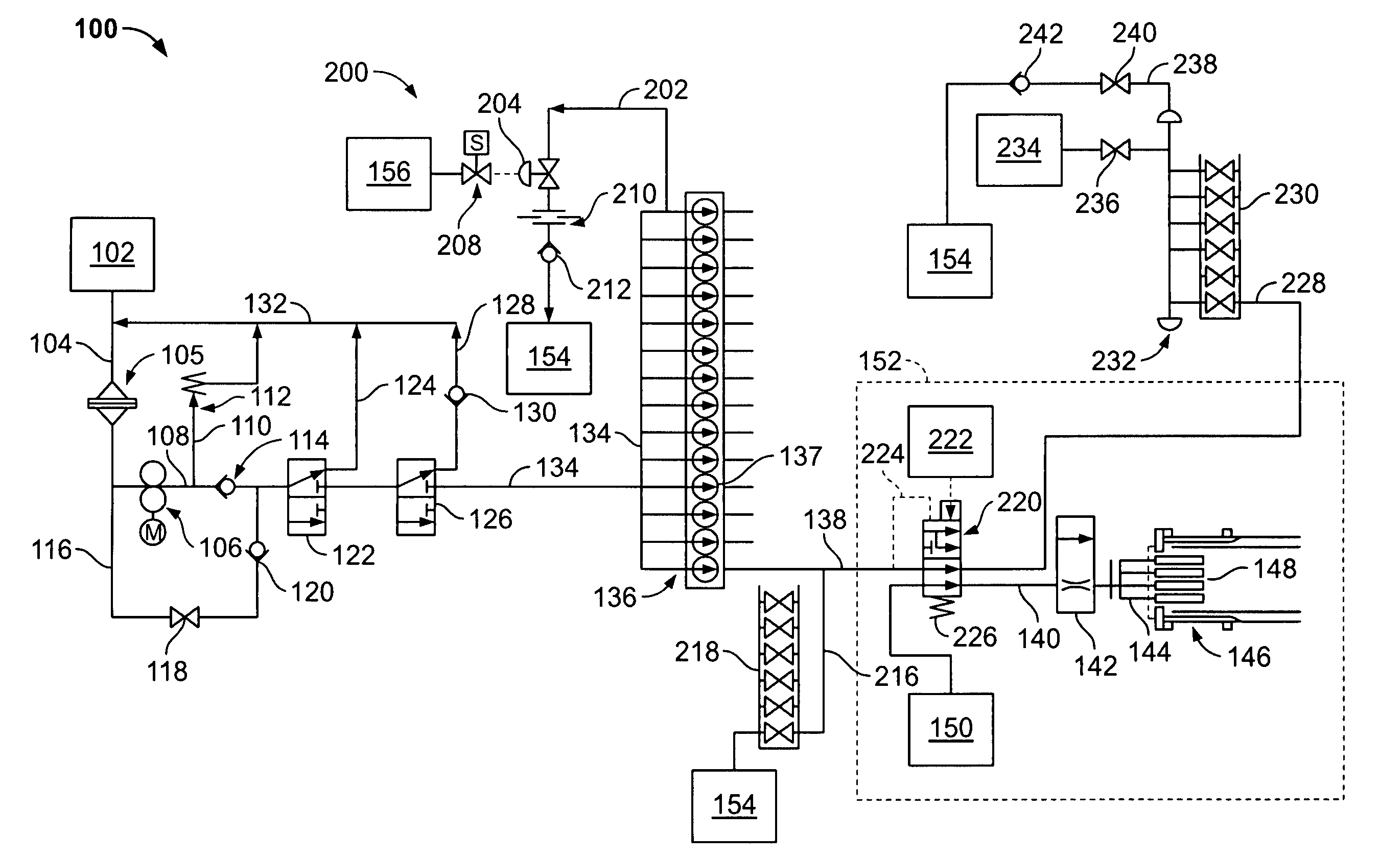
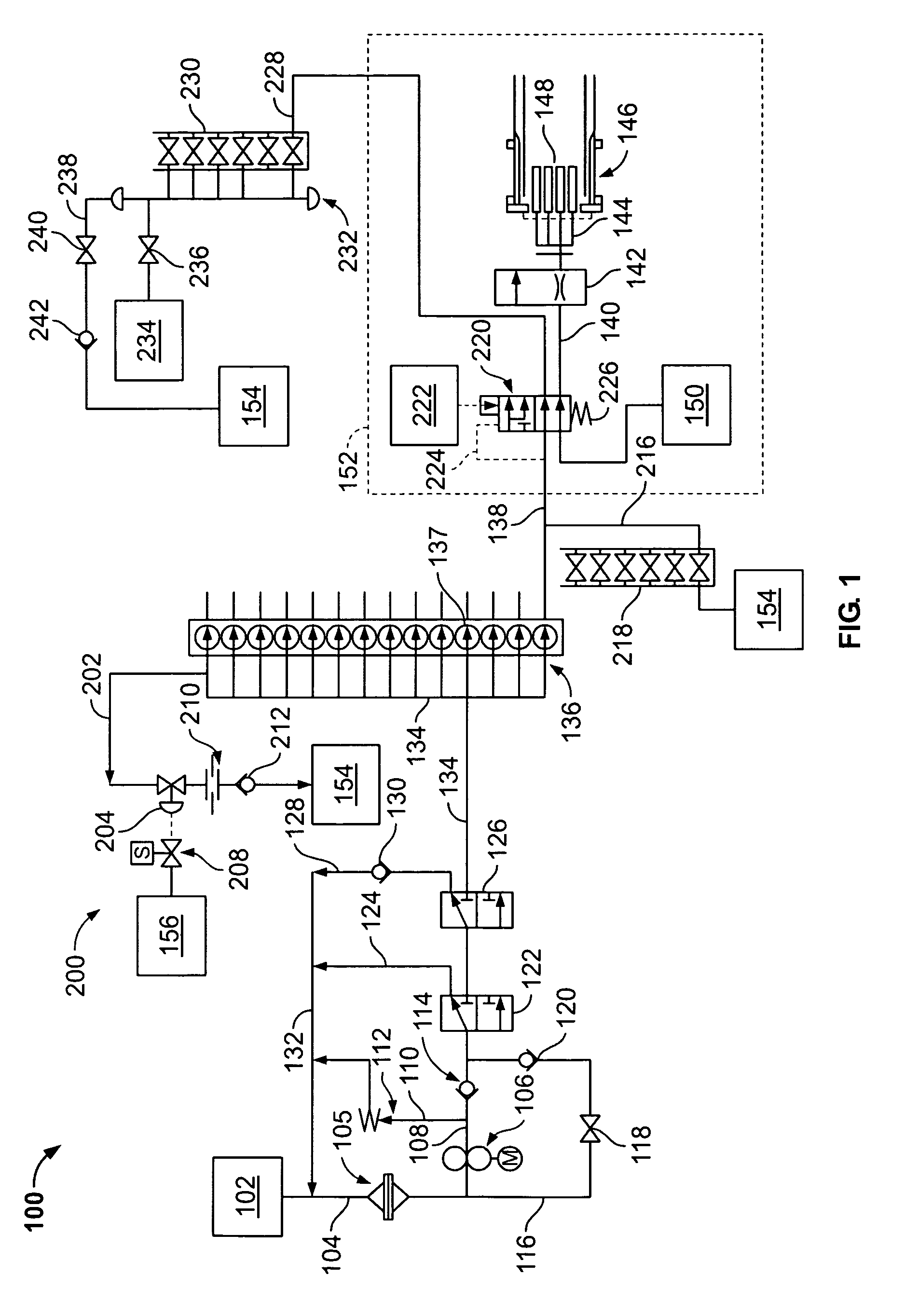
[0012]FIG. 1 is a schematic illustration of an exemplary embodiment of a liquid fuel system 100 having a nitrogen purge sub-system 200. Liquid fuel system 100 has at least one cavity that includes piping, headers, and tanks that further include a liquid fuel forwarding sub-system 102, a fuel pump suction header 104, at least one liquid fuel filter 105, a fuel pump 106, a fuel pump discharge header 108, a fuel pump discharge pressure relief valve header 110, a fuel pump discharge pressure relief valve 112, a fuel pump discharge check valve 114, a fuel pump bypass header 116, a bypass header manual blocking valve 118, a fuel pump bypass header check valve 120, a liquid fuel flow control valve 122, a control valve recirculation header 124, a liquid fuel flow stop valve 126, a stop valve recirculation header 128, a stop valve recirculation line check valve 130, a common recirculation header 132, a flow divider suction header 134, a flow divider 136 including at least one non-driven gear...


PUM


Abstract

A method of operating a fuel system is provided. The method includes removing fuel from at least a portion of the fuel system using a gravity drain process. The method also includes channeling nitrogen into at least a portion of the fuel system to facilitate removing air and residual fuel from at least a portion of the fuel system, thereby mitigating a formation of carbonaceous precipitate particulates. The method further includes removing air and nitrogen from at least a portion of the fuel system during a fuel refilling process using a venting process, such that at least a portion of the fuel system is substantially refilled with fuel and substantially evacuated of air and nitrogen. The method also includes removing air from at least a portion of the refilled fuel system using a venting process.

Description

BACKGROUND OF THE INVENTION[0001]This invention relates generally to rotary machines and, more particularly, to nitrogen purge sub-systems.[0002]In some known dual-fuel combustion turbines, the turbine is powered by burning either a gaseous fuel or a liquid fuel, the latter fuel typically being distillate oil. These combustion turbines have fuel supply systems for both liquid and gas fuels. Combustion turbines generally do not burn both gas and liquid fuels at the same time. Rather, when the combustion turbine burns liquid fuel, the gas fuel supply is removed from service. Alternatively, when the combustion turbine burns gaseous fuel, the liquid fuel supply is removed from service.[0003]In some known industrial combustion turbines, a combustion system may have an array of combustion cans, each of which has at least one liquid fuel nozzle and at least one gas fuel nozzle. In the combustion can arrangement, combustion is initiated within the combustion cans at a point slightly downstr...

Claims


Application Information

Patent Timeline
Patent Type & Authority Patents(United States)
IPC IPC(8): F02G3/00
CPCF01D25/007F02C7/232F02C7/30F23K5/06F23K5/04F05D2260/602F23K2301/203F05D2240/35F23K2300/203
Inventor KUNKLE, KEVIN LEEBACKMAN, STEVEN WILLIAMSMITH, DAVID WILLIAM
Owner GE INFRASTRUCTURE TECH INT LLC
Why Eureka
Try Eureka