A Method for Recognition of Impact Position on Composite Laminates

A composite material layer and composite material technology, which is applied in the field of impact position recognition, can solve the problems of large impact positioning errors, etc., and achieve the effect of reducing errors and simple operation

Active Publication Date: 2020-08-28
BEIJING AERONAUTIC SCI & TECH RES INST OF COMAC +1
View PDF9 Cites 0 Cited by
  • Summary
  • Abstract
  • Description
  • Claims
  • Application Information

AI Technical Summary

Problems solved by technology

At the same time, the method uses multi-frequency positioning technology, which overcomes the defect of large impact positioning error due to inaccurate measurement of wave arrival time at certain frequencies in the process of using single-frequency positioning technology

Method used


Image

  • A Method for Recognition of Impact Position on Composite Laminates
  • A Method for Recognition of Impact Position on Composite Laminates
  • A Method for Recognition of Impact Position on Composite Laminates

Examples


Embodiment Construction

[0044] In order to make the object, technical solution and advantages of the present invention clearer, the present invention will be further described in detail below in combination with specific embodiments and with reference to the accompanying drawings. It should be understood that these descriptions are exemplary only, and are not intended to limit the scope of the present invention. Also, in the following description, descriptions of well-known structures and techniques are omitted to avoid unnecessarily obscuring the concept of the present invention.

[0045] figure 1 It is a flow chart of the first embodiment of the method for identifying the impact position of a composite material laminate provided by the present invention.

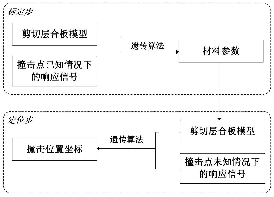
[0046] Such as figure 1 As shown, the impact location recognition method for composite laminates includes the following two steps:

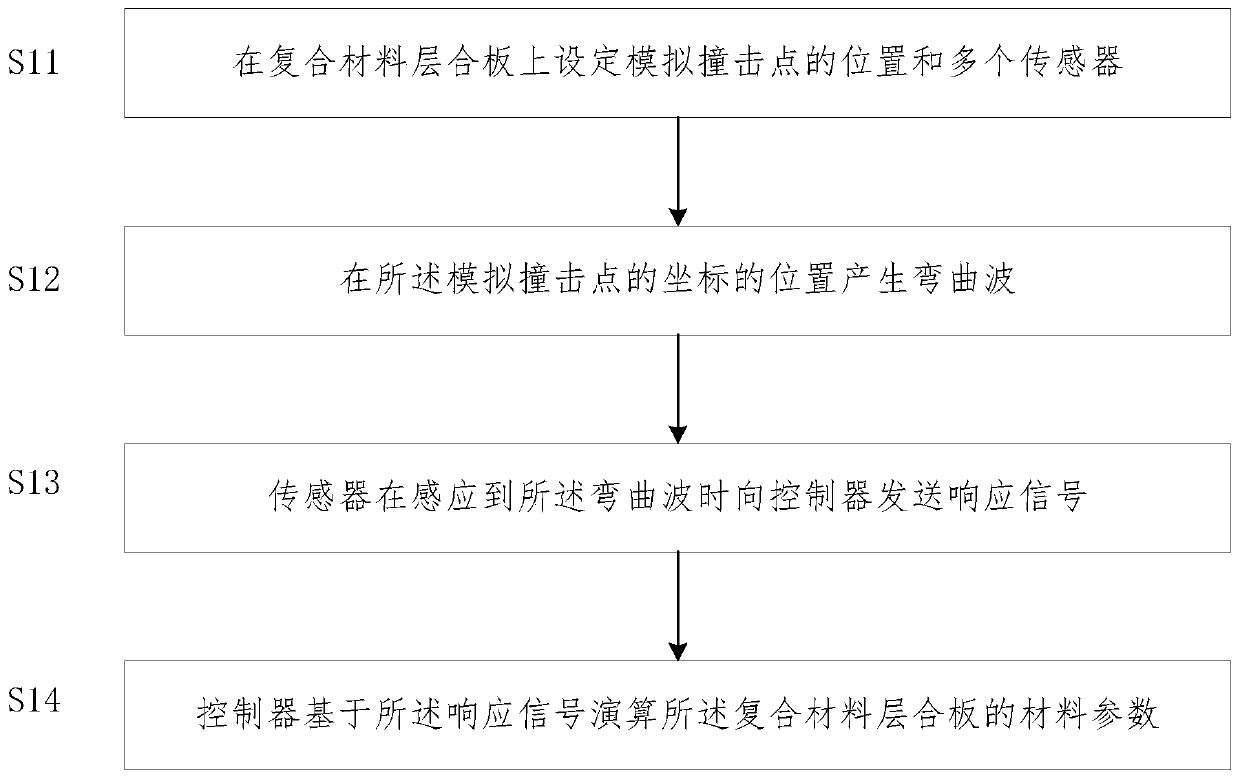
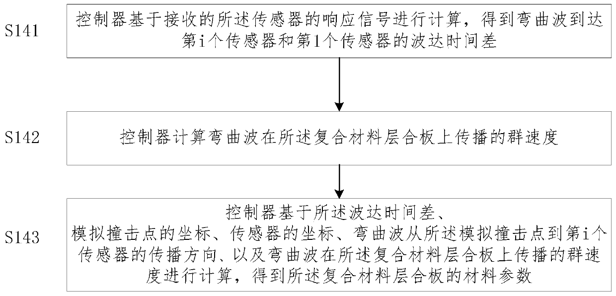
[0047] S1 calibration step: set the simulated impact point on the composite laminate, and calculate the materi...


PUM


Abstract

The invention discloses a method for recognizing the impact position of a composite laminated plate, and belongs to the technical field of aircrafts. The method comprises a calibration step and a positioning step. In the calibration step, the position of a simulated impact point and a plurality of sensors are set on the composite laminated plate; bending waves are generated at the position of thecoordinates of the simulated impact point; the sensors send response signals to a controller when sensing the bending waves; and the controller calculates material parameters of the composite laminated plate based on the response signals; and in the positioning step, the position of an actual impact point on the composite laminated plate is calculated based on the material parameters obtained in the calibration step. According to the invention, the variation of wave velocity in different directions is described by using a sheared laminated plate theoretical model, and the difficulty of wave velocity anisotropy is overcome. The material parameters of the model are periodically calibrated before a monitored structure is actually applied or according to requirements so as to ensure the accuracy of impact monitoring. Meanwhile, the method applies a multi-frequency positioning technology and overcomes a defect of great impact positioning errors caused by inaccurate measurement of the time or arrival under some frequencies.

Description

technical field [0001] The invention relates to the technical field of aircraft, in particular to a method for identifying the impact position of a composite material laminate. Background technique [0002] When a composite laminate is subjected to a low-velocity external impact, debonding damage occurs between the inner layers, while the outer surface has no obvious dents. Therefore, real-time impact monitoring of composite laminate structures is an important means to ensure their integrity and improve their safety. [0003] In the prior art, impact monitoring methods can be mainly divided into two categories: time-of-arrival-based methods and sample-based methods. Among them, the principle of the method based on the time of arrival is to use the piezoelectric ceramic sensor to receive the structural impact response signal, and determine the actual impact point position by extracting the time of arrival. Since the velocity of the elastic wave in isotropic materials is the...

Claims


Application Information

Patent Timeline
Patent Type & Authority Patents(China)
IPC IPC(8): G01P15/09
CPCG01P15/0922
Inventor 朱凯歌高丽敏
Owner BEIJING AERONAUTIC SCI & TECH RES INST OF COMAC
Why Eureka
Try Eureka