Sealing structure and forming method

A technology of sealing structure and sealing groove, which is applied in the direction of pipes/pipe joints/fittings, pipe connection arrangement, mechanical equipment, etc. Improved reliability and practical operability, simple injection molding process, improved sealing effect

Inactive Publication Date: 2018-08-28
宁波央腾汽车电子有限公司
View PDF6 Cites 1 Cited by
  • Summary
  • Abstract
  • Description
  • Claims
  • Application Information

AI Technical Summary

Problems solved by technology

Since the material of the plastic main part is different from that of the metal insert, their thermal expansion coefficients differ greatly. Gaps between metal inserts are prone to leaks
[0003] The current solutions are as follows: one is to add an annular groove outside the metal insert, such as figure 1 As shown, the metal insert 1a, the main plastic part 1b; the second is that the metal insert is coated with glue or heat-shrinkable tube and then injected, such as figure 2 As shown, the metal insert 2a and the main plastic part 2b; however, there are the following problems in the long-term use process: (1) the metal insert adds an annular groove or an injection-molded rubber-coated part. There will also be gaps between metal inserts, which are prone to leakage and low reliability; (2) The solution of metal inserts coated with glue or adding heat shrinkable tubes after injection molding, because the temperature during injection molding is greater than 300 degrees Celsius, generally sealed The temperature resistance of glue or heat-shrinkable tube cannot reach the high temperature aging failure phenomenon during injection molding, and the actual operability is not high

Method used


Image

  • Sealing structure and forming method
  • Sealing structure and forming method
  • Sealing structure and forming method

Examples


Embodiment Construction

[0031] The following will clearly and completely describe the technical solutions in the embodiments of the present invention with reference to the accompanying drawings in the embodiments of the present invention. Obviously, the described embodiments are only some, not all, embodiments of the present invention. Based on the embodiments of the present invention, all other embodiments obtained by persons of ordinary skill in the art without creative efforts fall within the protection scope of the present invention.

[0032] It should be noted that, in the case of no conflict, the embodiments of the present invention and the features in the embodiments can be combined with each other.

[0033] The present invention will be further described below in conjunction with the accompanying drawings and specific embodiments, but not as a limitation of the present invention.

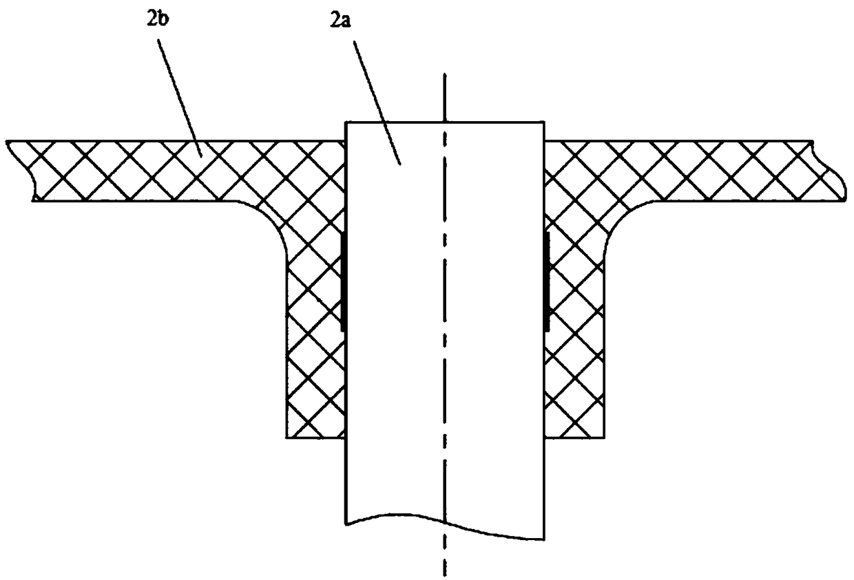
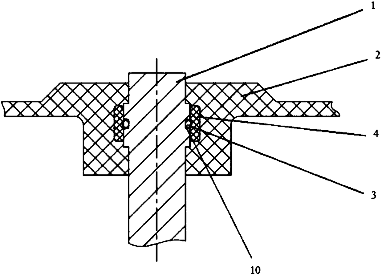
[0034] The present invention includes a sealing structure applied between the metal insert 1 and the main plasti...


PUM


Abstract

The invention discloses a sealing structure and a forming method. The sealing structure is applied between a metal insert part and a main body plastic part, and is characterized in that a sealing groove is formed in the metal insert part; a sealing ring is arranged on the sealing groove; a cylindrical plastic part sleeves on the outer side of the sealing ring; the main body plastic part is arranged on the outer side of the cylindrical plastic part; and the metal insert part, the cylindrical plastic part and the main body plastic part are hot melted through injection molding. The technical scheme provided by the invention has the beneficial effects that the sealing structure and the forming method are disclosed, the sealability between the main body plastic part and the metal insert part can be improved, the reliability and the actual operability of an injection process are further improved, and in injection molding process is simple in process and lower in cost.

Description

technical field [0001] The invention relates to the technical field of plastic sealing, in particular to a sealing structure. Background technique [0002] In the prior art, there are many parts with metal inserts on the main plastic part, and many parts require a seal between the main plastic part and the metal insert. Since the material of the plastic main part is different from that of the metal insert, their thermal expansion coefficients differ greatly. Gaps between metal inserts are prone to leaks. [0003] The current solutions are as follows: one is to add an annular groove outside the metal insert, such as figure 1 As shown, the metal insert 1a, the main plastic part 1b; the second is that the metal insert is coated with glue or heat-shrinkable tube and then injected, such as figure 2 As shown, the metal insert 2a and the main plastic part 2b; however, there are the following problems in the long-term use process: (1) the metal insert adds an annular groove or a...

Claims


Application Information

Patent Timeline
Patent Type & Authority Applications(China)
IPC IPC(8): F16L47/03
CPCF16L47/03
Inventor 李宁
Owner 宁波央腾汽车电子有限公司
Why Eureka
Try Eureka