Seating tool

A seat and an integrated technology, applied in the field of furniture, can solve the problems of high production cost, complex structure, and high matching requirements, and achieve the effects of improved service life and stability, small restoring force, and large tilting range

CN108514259APending Publication Date: 2018-09-11HENGLIN HOME FURNISHINGS CO LTD
1 Cites 1 Cited by

Patent Information

Authority / Receiving Office
CN · China
Patent Type
Applications(China)
Current Assignee / Owner
Publication Date
2018-09-11

Smart Images

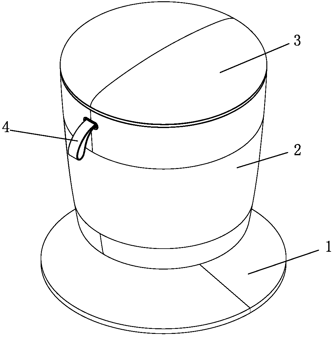
  • Figure 1
    Figure 1
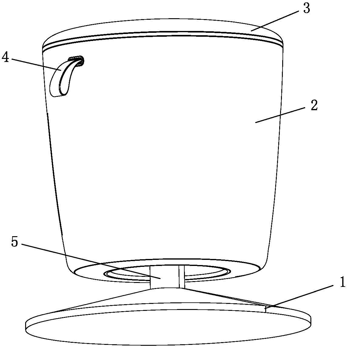
  • Figure 2
    Figure 2
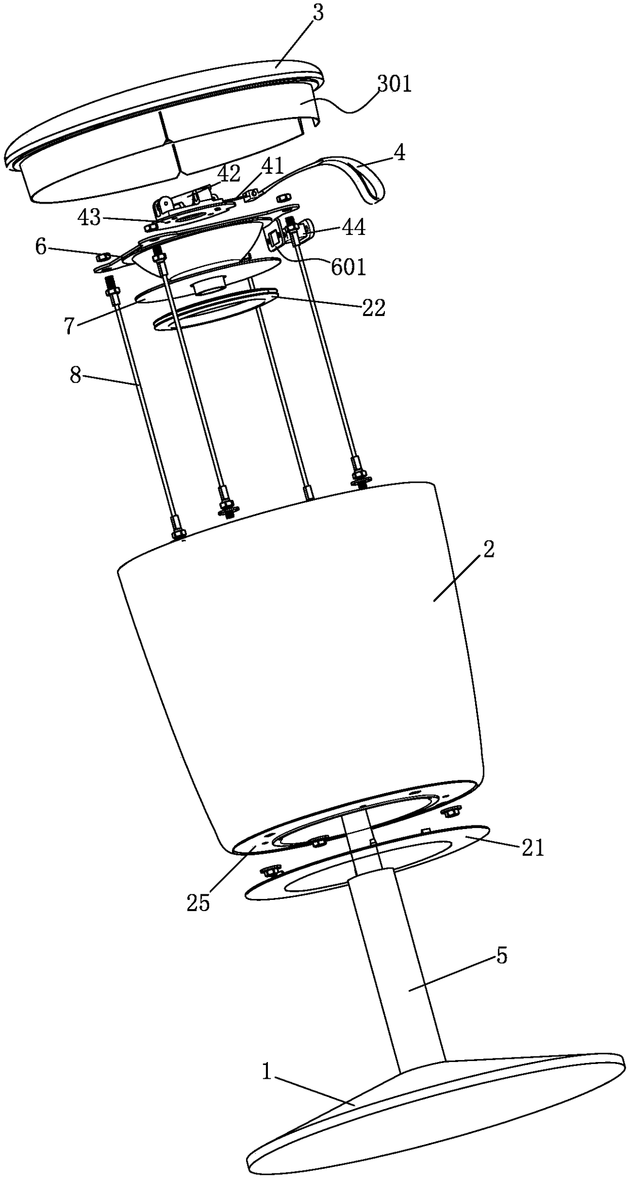
  • Figure 3
    Figure 3
Patent Text Reader

Abstract

The invention discloses a seating tool, which comprises a seat part, a support element and a base, wherein the lower end of the support element is arranged on the base; a plurality of hanging elementsare arranged on the support element; the bearing element is sleeved on the outside of the support element; a gap is formed between the bearing element and the support element; the plurality of hanging elements are distributed around the support element by using the support element as the center; the upper ends of the plurality of hanging elements are respectively connected with the support element; the lower ends of the plurality of hanging elements are respectively connected with the bearing element; the seat part is arranged on the bearing element; the seat part is positioned above the support element. By using the technical scheme, the support element does not directly bear the weight on the seat part; the conduction and stress is realized through the hanging elements and the bearing element; the support element does not bear the pressure from the upper side and bears the tension from the lower side. The hanging elements are used, so that great mobility is realized; in addition, the mobility of the hanging elements has the advantages of large inclination range, small restoration force, non-obvious guidance effect, failure difficulty and the like; the service life of the seatingtool is prolonged; the stability of the seating tool is improved.
Need to check novelty before this filing date? Find Prior Art

Description

technical field

[0001] The invention relates to the field of furniture, in particular to a seat. Background technique

[0002] The lift chair is mainly composed of a seat, a base, a lifting positioning device and a chair foot. Since the seat of the lift chair can be lifted, it can be adapted to people of different heights for sitting or standing. For example, the lift chairs disclosed in patent documents such as CN2862841 and CN204950158 include seat cushions, chair feet, air rods and air rod control parts. The pneumatic rod control part is connected, and the switch of the pneumatic rod is controlled by pulling the pneumatic rod control part to realize lifting. However, the structure of the lift chair in the prior art is generally not suitable for the user to swing from side to side or lean back and forth, and cannot provide effective and reliable support when the user adjusts the sitting posture, and the air rod and its control parts are exposed, and the appearance is not...

Examples

Embodiment Construction

[0030] Embodiments of the present invention are described in detail below, examples of which are shown in the drawings, wherein the same or similar reference numerals designate the same or similar elements or elements having the same or similar functions throughout. The embodiments described below by referring to the figures are exemplary and are intended to explain the present invention and should not be construed as limiting the present invention.

[0031] In describing the present invention, it should be understood that the terms "center", "longitudinal", "transverse", "length", "width", "thickness", "upper", "lower", "front", " The orientations or positional relationships indicated by "rear", "left", "right", "vertical", "horizontal", "top", "bottom", "inner", "clockwise", "counterclockwise" are based on the attached The orientation or positional relationship shown in the figure is only for the convenience of describing the present invention and simplifying the description...