Rotor core and motor of a magnetic circuit series hybrid permanent magnet controllable flux motor

A technology of rotor iron core and hybrid permanent magnet, which is applied in the direction of magnetic circuit rotating parts, magnetic circuit, synchronous motor with stationary armature and rotating magnet, etc. It can solve the problem of easy demagnetization at the working point of low coercivity permanent magnet Problems, achieve a large flux linkage adjustment range, increase the operating point and magnetization degree, and reduce the effect of magnetizing current

Active Publication Date: 2020-05-19
HUAZHONG UNIV OF SCI & TECH
View PDF12 Cites 0 Cited by
  • Summary
  • Abstract
  • Description
  • Claims
  • Application Information

AI Technical Summary

Problems solved by technology

[0005] Aiming at the above defects or improvement needs of the prior art, the present invention provides a rotor core and motor of a magnetic circuit series hybrid permanent magnet controllable flux motor, aiming to solve the problem of existing hybrid permanent magnet controllable flux motors. The equivalent magnetic circuit is parallel type, which leads to the technical problem that the working point of the low coercivity permanent magnet is lowered and the phenomenon of easy demagnetization occurs.

Method used


Image

  • Rotor core and motor of a magnetic circuit series hybrid permanent magnet controllable flux motor
  • Rotor core and motor of a magnetic circuit series hybrid permanent magnet controllable flux motor
  • Rotor core and motor of a magnetic circuit series hybrid permanent magnet controllable flux motor

Examples


Embodiment Construction

[0022] In order to make the object, technical solution and advantages of the present invention clearer, the present invention will be further described in detail below in conjunction with the accompanying drawings and embodiments. It should be understood that the specific embodiments described here are only used to explain the present invention, not to limit the present invention. In addition, the technical features involved in the various embodiments of the present invention described below can be combined with each other as long as they do not constitute a conflict with each other.

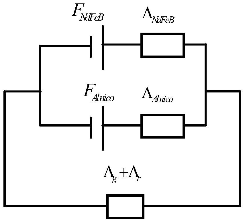
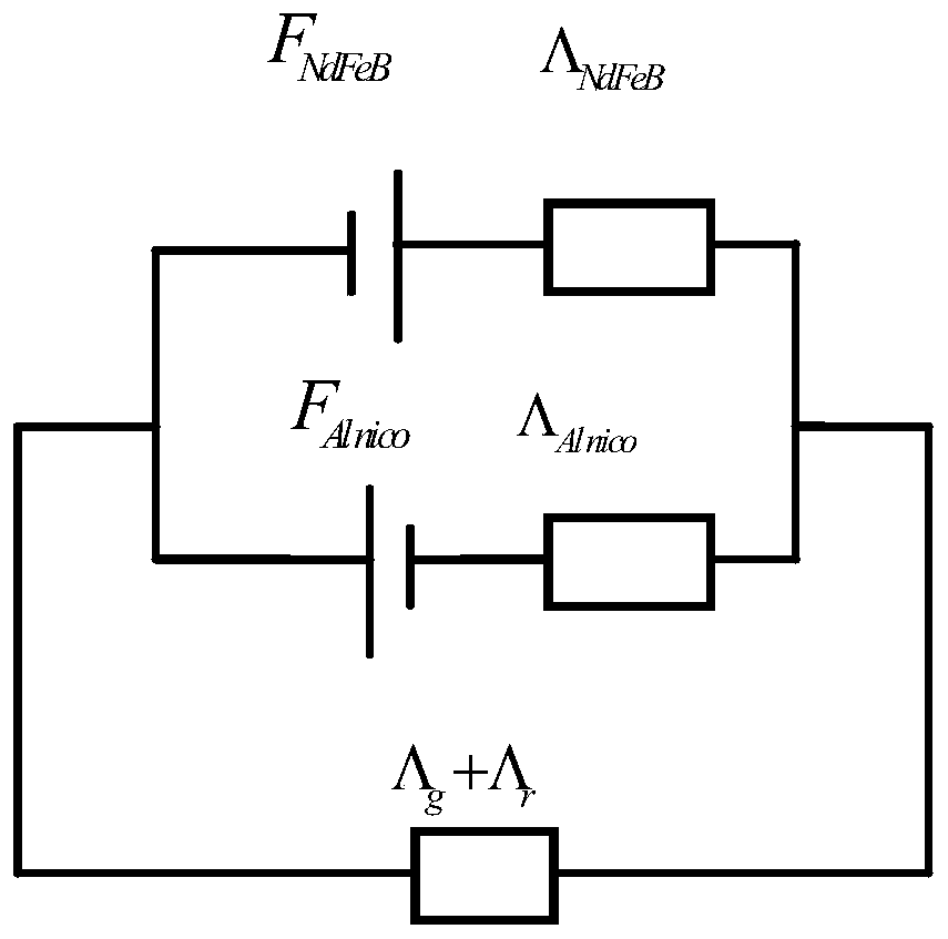
[0023] In the shunt controllable flux motor, as shown in Fig. 1(a), F NdFeB Indicates the magnetomotive force of NdFeB, that is, the magnetomotive force of a permanent magnet with low coercive force, Λ NdFeB Indicates the permeance of NdFeB, that is, the permeance of permanent magnets with low coercive force, F Alnico Indicates the AlNiCo magnetomotive force, that is, the magnetomotive force o...


PUM


Abstract

The invention discloses a rotor iron core and motor of a hybrid permanent magnet controllable flux motor with series magnetic circuits. A permanent magnet for tangent magnetizing and two permanent magnets for radial magnetizing are arranged under each pole of the rotor iron core, the permanent magnet for tangent magnetizing is arranged as the spoke and far away from the air gap; the two permanentmagnets for radial magnetizing are located at two sides of the permanent magnet for tangent magnetizing; the included angle between each permanent magnet for radial magnetizing and the permanent magnet for tangent magnetizing is not more than 90 DEG; the permanent magnet for radial magnetizing is the high-coercivity permanent magnet or the low-coercivity permanent magnet, the permanent magnet fortangent magnetizing is the high-coercivity permanent magnet or the low-coercivity permanent magnet, and the permanent magnet types of the permanent magnet for radial magnetizing and the permanent magnet for tangent magnetizing are different. By adopting the series magnetic circuit structure, the magnetizing effect of the low-coercivity permanent magnet is enhanced, the magnetizing current of the motor is reduced, the working point of the permanent magnet is improved, and the torque output of the motor is increased.

Description

technical field [0001] The invention belongs to the field of motors, and more specifically relates to a rotor core and a motor of a magnetic circuit series hybrid permanent magnet controllable flux motor. Background technique [0002] Due to its high power density, high efficiency, and good mechanical properties, permanent magnet synchronous motors have received extensive attention and applications in industry, national defense, and daily life. In traditional permanent magnet motors, as the speed continues to increase, the no-load back electromotive force continues to increase. In order to ensure that the motor terminal voltage does not exceed the voltage limit that the inverter can output, it is necessary to use field weakening control, that is, by increasing The direct axis demagnetization current component is used to offset the magnetomotive force of the permanent magnet, maintain the voltage balance during high-speed operation, and achieve the purpose of weakening the ma...

Claims


Application Information

Patent Timeline
Patent Type & Authority Patents(China)
IPC IPC(8): H02K1/27H02K21/14
CPCH02K1/2766H02K21/14H02K2213/03
Inventor 李健葛梦
Owner HUAZHONG UNIV OF SCI & TECH
Why Eureka
Try Eureka