Welding workbench for electronic product machining

A technology for electronic products and workbenches, applied in welding equipment, metal processing equipment, manufacturing tools, etc., can solve the problems of welding workbenches that do not have tin collecting devices, workers' health effects, and inconvenience for post-cleaning, etc., to achieve flexible rotation. , Enhance the practicability and facilitate the effect of welding

Inactive Publication Date: 2018-10-02
芜湖通全电子电器科技创业有限公司
View PDF8 Cites 4 Cited by
  • Summary
  • Abstract
  • Description
  • Claims
  • Application Information

AI Technical Summary

Problems solved by technology

[0002] During the processing of electronic products, welding workbenches are used to complete the welding operation. Most of the existing welding workbenches have simple structures and single functions. Workers need to manually hold the objects to be welded during welding. The effect is poor, and it is also prone to burns, and the smoke generated during the welding process will also affect the health of the workers, and the safety is poor. In addition, most welding workbenches do not have tin collecting devices, and welding produces The welding slag is often covered on the work surface, which is not only inconvenient to clean up later, but also causes a waste of resources, which in turn leads to an increase in production costs and low practicability

Method used


Image

  • Welding workbench for electronic product machining
  • Welding workbench for electronic product machining
  • Welding workbench for electronic product machining

Examples


Embodiment Construction

[0022] The following will clearly and completely describe the technical solutions in the embodiments of the present invention with reference to the accompanying drawings in the embodiments of the present invention. Obviously, the described embodiments are only some, not all, embodiments of the present invention. Based on the embodiments of the present invention, all other embodiments obtained by persons of ordinary skill in the art without making creative efforts belong to the protection scope of the present invention.

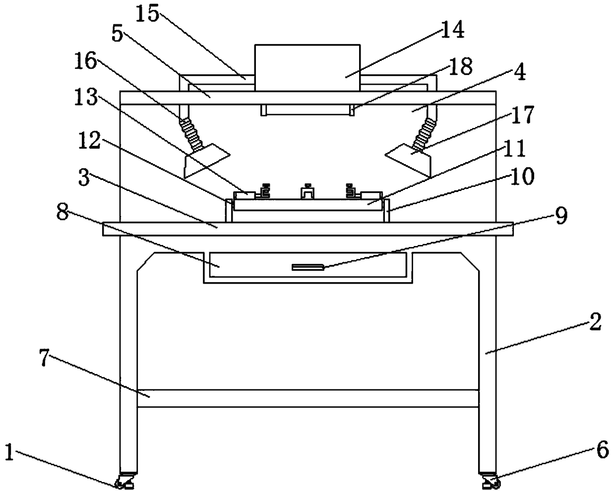
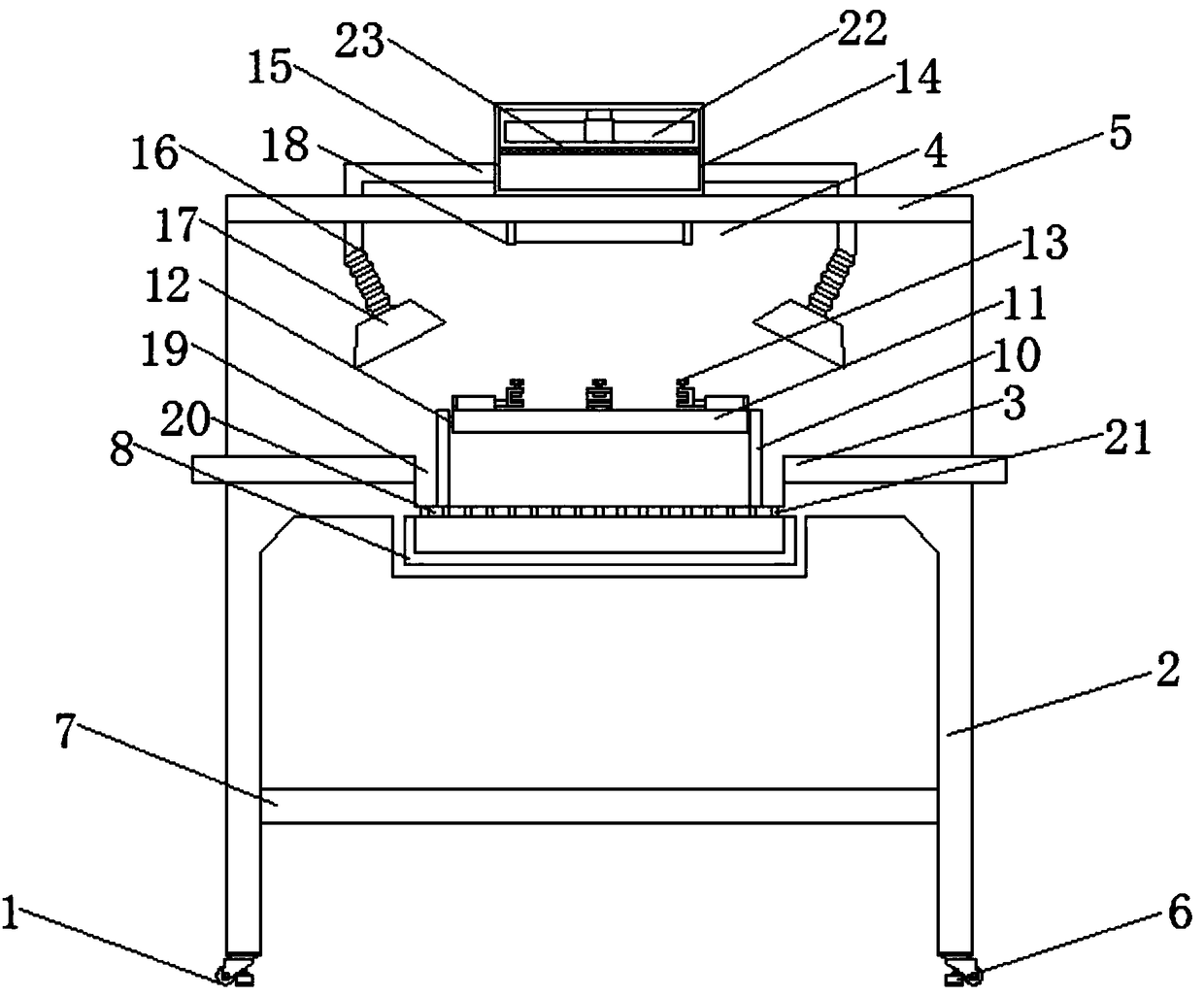
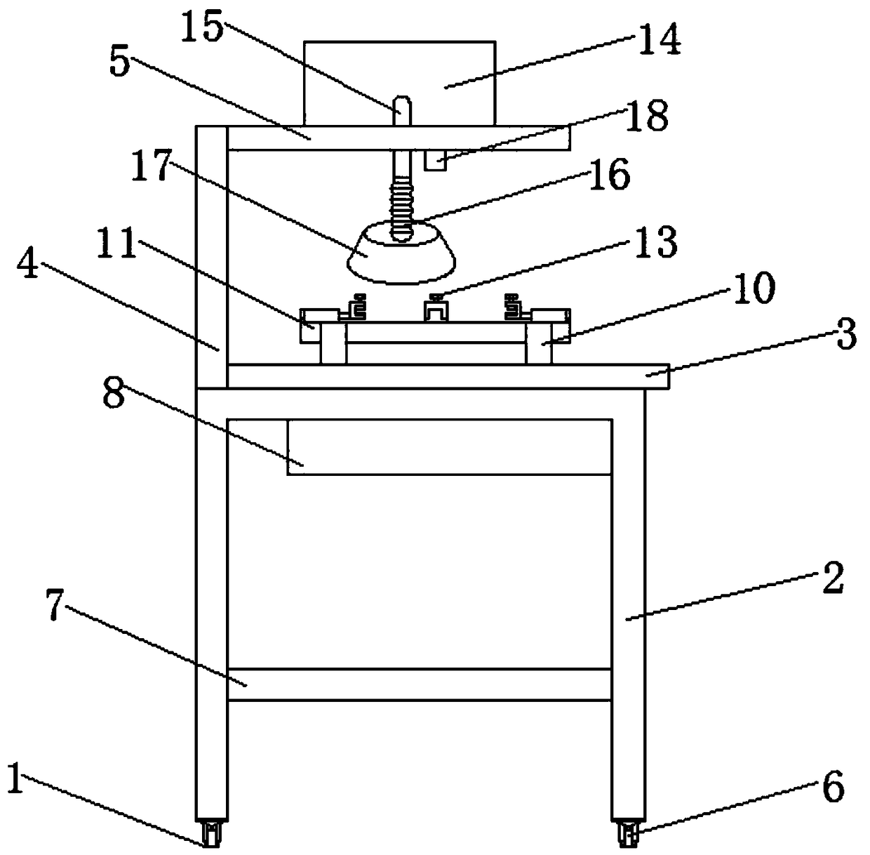
[0023] see Figure 1-5 , the present invention provides a technical solution: a welding workbench for electronic product processing, including a workbench body 1, a stand 2, a table top 3, a vertical plate 4, a top plate 5, casters 6, a reinforcing rod 7, and a tin collecting drawer 8 , slot 9, support plate 10, welding plate 11, rotating shaft 12, fixer 13, smoking box 14, smoking pipe 15, universal telescopic tube 16, smoking hood 17, lighting lamp 18, groov...


PUM


Abstract

The invention discloses a welding workbench for electronic product machining. A table frame is arranged at the bottom of a workbench body; a table surface is installed at the top of the table frame; agroove is formed in the middle part of the table surface; a bottom plate is arranged at the bottom end of the groove; support plates are installed at the two ends of each of the two sides of the topof the bottom plate; a rotary shaft is installed at the top end of each support plate; a welding plate is installed at one end of each rotary shaft; a fixer is installed around the top of each weldingplate; a tin collection drawer is installed at the bottom of the bottom plate; a vertical plate is installed on the back surface of the table surface; a top plate is installed at the top of the vertical plate; a smoke extraction box is installed at the top of the top plate; a smoke extraction machine is installed at the top end in the smoke extraction box; smoke extraction pipes are installed atthe bottom ends of the two sides of the smoke extraction box; a universal telescopic pipe is fixedly connected to the bottom end of each smoke extraction pipe; a smoke absorption cover is installed atthe bottom of each universal telescopic pipe; an illumination lamp is installed on the bottom surface of the top plate; and castors are installed at the bottom of the table frame. According to the welding workbench for electronic product machining, a filter screen is installed at the bottom of the smoke extraction machine, so that filtering for the smoke generated due to welding is facilitated; and the welding workbench for electronic product machining is simple and practical, and secondary pollution is avoided.

Description

technical field [0001] The invention relates to the technical field of electronic product processing devices, in particular to a welding workbench for electronic product processing. Background technique [0002] During the processing of electronic products, welding workbenches are used to complete the welding operation. Most of the existing welding workbenches have simple structures and single functions. Workers need to manually hold the objects to be welded during welding. The effect is poor, and it is also prone to burns, and the smoke generated during the welding process will also affect the health of the workers, and the safety is poor. In addition, most welding workbenches do not have tin collecting devices, and welding produces The welding slag is often covered on the work surface, which is not only inconvenient to clean up later, but also causes a waste of resources, which in turn leads to an increase in production costs and low practicability. [0003] Therefore, it...

Claims


Application Information

Patent Timeline
Patent Type & Authority Applications(China)
IPC IPC(8): B23K3/08B08B15/02
CPCB08B15/02B23K3/08
Inventor 汤佳季一全
Owner 芜湖通全电子电器科技创业有限公司
Why Eureka
Try Eureka