Ultrasonic mechanical linear scan probe with vibration-reduction function

A linear scanning and mechanical technology, applied in the field of scanning probes, can solve problems such as waste of resources, large vibration of ultrasonic probes, and image quality effects, and achieve the effect of reducing mechanical vibration and improving image quality.

Pending Publication Date: 2018-11-09
INST OF BIOMEDICAL ENG CHINESE ACAD OF MEDICAL SCI +1
View PDF11 Cites 2 Cited by
  • Summary
  • Abstract
  • Description
  • Claims
  • Application Information

AI Technical Summary

Problems solved by technology

However, the scanning performed by this method is usually not uniform, and the linear motion speed of the ultrasonic transducer is in a sinusoidal mode. If sampling at equal time intervals is used, the sampling lines in the scanning area will be dense on both sides and sparse in the middle. When such a scanning sampling line is used to reconstruct a two-dimensional ultrasound image, the area with dense sampling line will be eliminated to a certain extent, and the area with sparse sampling line will be artificially interpolated, which will not only cause waste of resources, but also affect the image quality.
[0005] Due to the large stroke of the mechanical linear scan, it will cause a large vibration of the ultrasonic probe

Method used


Image

  • Ultrasonic mechanical linear scan probe with vibration-reduction function
  • Ultrasonic mechanical linear scan probe with vibration-reduction function
  • Ultrasonic mechanical linear scan probe with vibration-reduction function

Examples


Embodiment Construction

[0041] A vibration-reducing ultrasonic mechanical linear scanning probe of the present invention will be described in detail below in conjunction with the embodiments and the accompanying drawings.

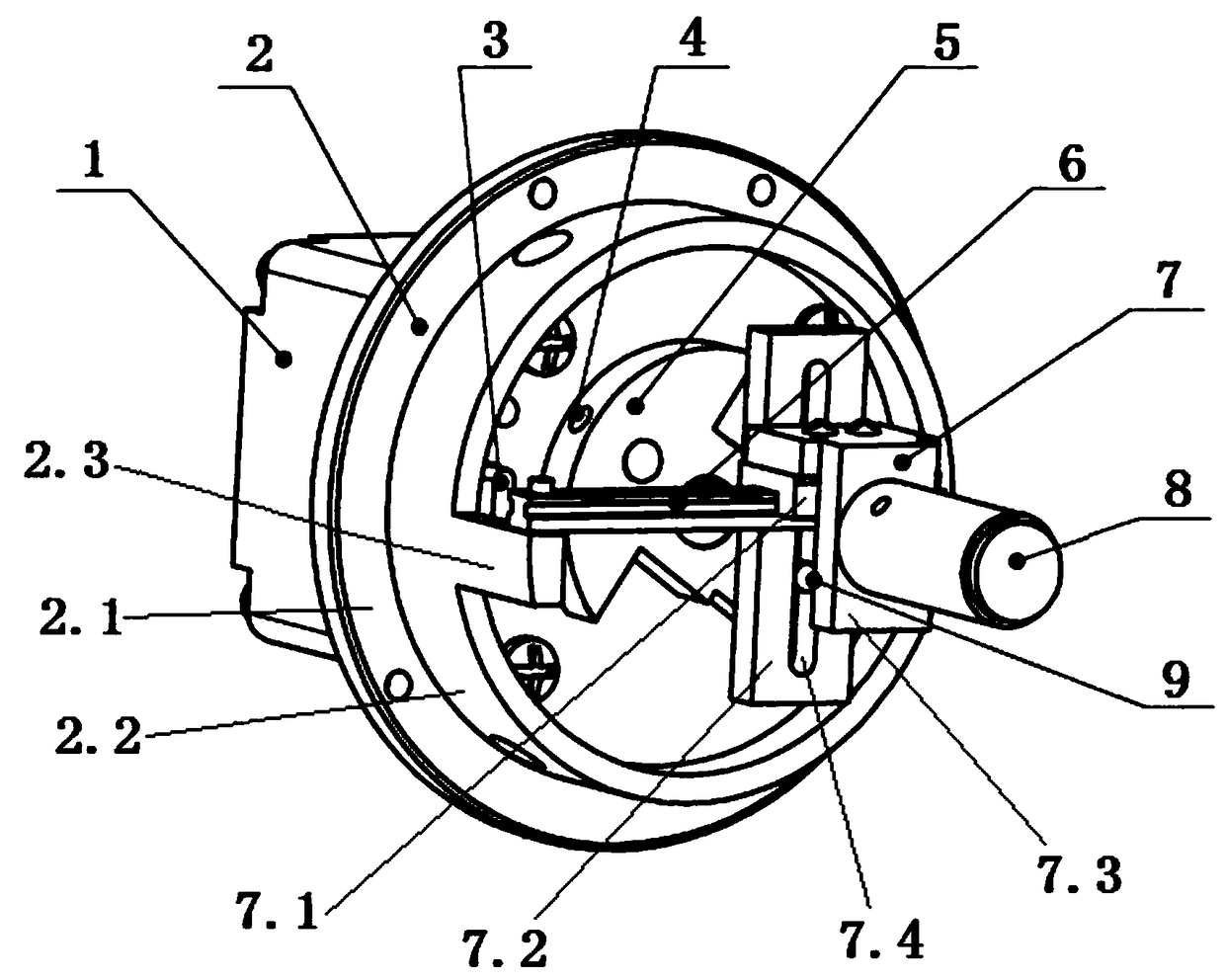
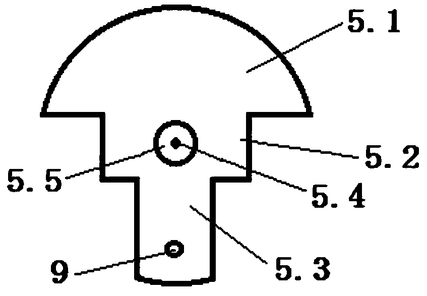
[0042] Such as figure 1 As shown, an ultrasonic mechanical linear scanning probe capable of reducing vibration of the present invention includes a stepper motor 1 and a probe main frame body 2, and the probe main frame body 2 is integrally connected to the chassis 2.1 by a chassis 2.1 The main body ring 2.2 constitutes that the diameter of the chassis 2.1 is larger than the diameter of the main body ring 2.2. The chassis 2.1 is fixedly connected to the front end surface of the stepper motor 1 by screws, the motor shaft of the stepper motor 1 runs through the chassis 2.1 and is fixedly connected to the eccentric wheel 5 located inside the main body ring 2.2, and the main body ring The front port of 2.2 is provided with a linear guide rail 6 horizontally along the diameter. A tran...


PUM


Abstract

The invention provides an ultrasonic mechanical linear scan probe with a vibration-reduction function. A probe main frame is composed of a base plate and a main ring which is integrally connected to the surface of the base plate, the base plate is fixedly connected to the front end surface of a stepping motor through bolts, and a motor shaft of the stepping motor penetrates through the base plateand is fixedly connected with an eccentric gear which is located in the main ring. A front end opening of the main ring is horizontally provided with a linear guide rail along the diameter, the linearguide rail is provided with a transducer stand, the front end of the transducer stand is fixedly provided with an ultrasonic transducer, and the eccentric gear is provided with a deflector rod whichis used for driving the transducer stand to move along the linear guide rail. By means of the ultrasonic mechanical linear scan probe as a two-dimensional ultrasonic probe, high-quality and high-frequency ultrasonic images can be obtained; the probe can effectively reduce mechanical vibration brought during mechanical linear scanning of the probe; under the condition that a driving motor unidirectionally rotates at the constant speed, and the linear movement speed of the ultrasonic transducer is in a sine mode, it is achieved that sampling is uniformly conducted in a linear scanning range at equal space intervals, and the starting position of the ultrasonic transducer can be accurately detected when the ultrasonic transducer collects the images.

Description

technical field [0001] The invention relates to a scanning probe. In particular, it relates to an ultrasonic mechanical linear scanning probe capable of reducing vibration. Background technique [0002] High-frequency ultrasound generally refers to ultrasound with a center frequency greater than 10MHz. High-frequency ultrasound is of great significance in the diagnosis of superficial organ diseases such as the skin, thyroid, and eyes due to its extraordinary resolution. The lateral resolution and axial resolution of high-frequency ultrasound images determine the quality of high-frequency ultrasound imaging. The lateral resolution of high-frequency ultrasound images is related to the interval of sound beams. The thinner the sound beam, the better the lateral resolution. Good; the axial resolution of high-frequency ultrasound images is proportional to the center frequency of the transducer, the higher the center frequency, the better the axial resolution. [0003] At present...

Claims


Application Information

Patent Timeline
Patent Type & Authority Applications(China)
IPC IPC(8): A61B8/00
CPCA61B8/4461A61B8/4483
Inventor 杨军王文赛宋学东高璇周盛王晓春
Owner INST OF BIOMEDICAL ENG CHINESE ACAD OF MEDICAL SCI
Why Eureka
Try Eureka