Control circuit and control method

A technology of control circuit and control method, applied in the direction of program control, computer control, general control system, etc., can solve the problems of insufficient interface and increase production cost, so as to reduce production input cost, save interface resources, and improve interface utilization rate. Effect

Active Publication Date: 2019-11-08
QINGDAO HISENSE HITACHI AIR CONDITIONING SYST
View PDF16 Cites 0 Cited by
  • Summary
  • Abstract
  • Description
  • Claims
  • Application Information

AI Technical Summary

Problems solved by technology

[0002] At present, in the design of control boards of electronic products, most of the main control chips are used, and it is usually necessary to use more pins of the main control chip to realize the functions of input detection and output display (or control), so it is often encountered that the main control chip The input / output (in / out, I / O) interface of the control chip is not enough, which brings great trouble to the designer. If the replacement of the main control chip with more I / O will increase the production cost

Method used


Image

  • Control circuit and control method
  • Control circuit and control method
  • Control circuit and control method

Examples


Embodiment 1

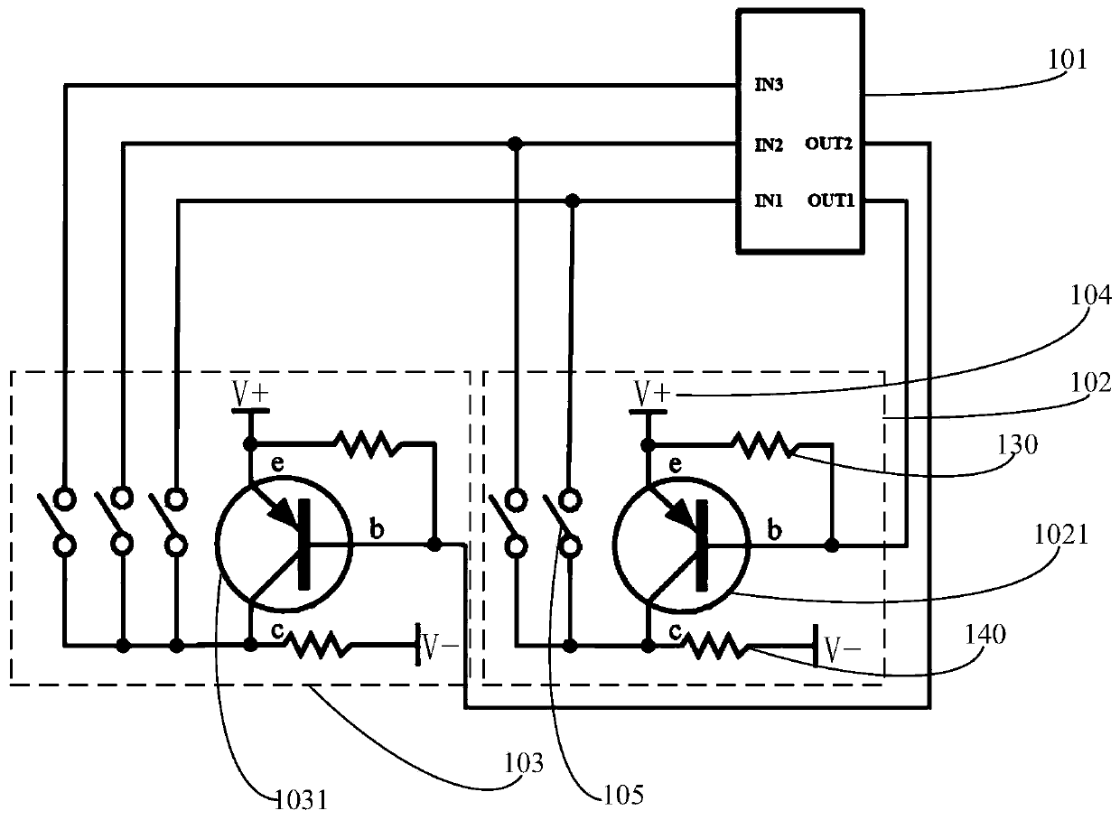
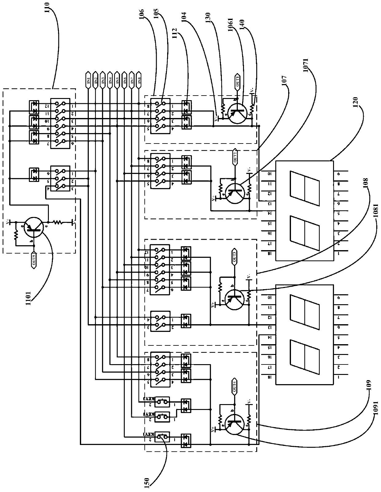
[0020] The control circuit provided by the embodiment of the present invention includes: a main control chip, a plurality of switch modules and a power supply, each switch module includes a plurality of switches and triodes, the main control chip includes a plurality of input terminals and a plurality of output terminals, wherein, The number of output terminals is equal to the number of multiple switch modules, the number of input terminals is equal to the number of switches in the first switch module, and the first switch module is the switch module with the largest number of switches among the multiple switch modules; the triode of each switch module The base is correspondingly connected to one of the output terminals, the emitter of the triode of each switch module is connected to the first pole of the power supply, and the collector of the triode of each switch module is connected to the second pole of the power supply; in each switch module The first end of each switch is ...

Embodiment 2

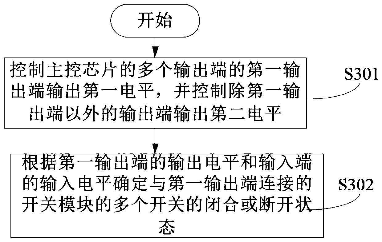
[0062] For the control method provided by the embodiment of the present invention, refer to image 3 As shown in , the control method includes:

[0063] S301. Control a first output terminal of a plurality of output terminals of the main control chip to output a first level, and control output terminals other than the first output terminal to output a second level.

[0064] S302. Determine, according to the output level of the first output terminal and the input level of the input terminal, the closed or open states of the plurality of switches of the switch module connected to the first output terminal.

[0065] optional, see Figure 4 As shown in the S301 includes:

[0066] S401. If the transistor of the switch module of the control circuit is a PNP transistor, control the first output terminal of the multiple output terminals to output a low level, and control the output terminals other than the first output terminal to output a high level.

[0067] S402. If the transistor...


PUM


Abstract

The invention discloses a control circuit and a control method, which relate to the technical field of interfaces of a main control chip and are used for realizing that the main control chip controls more functional modules with fewer interfaces so as to reduce costs. The control circuit includes a main control chip, a plurality of switch modules and a power supply, the switch module includes a triode and a plurality of switches, the number of output ends of the main control chip is equal to the number of switch modules, and the number of input ends is equal to the maximum number of switches in a single switch module Equal; the base of the triode of the switch module is connected to one of the output terminals, the emitter of the triode is connected to the first pole of the power supply, and the collector of the triode is connected to the second pole of the power supply; the first terminal of each switch in the switch module Connected to the collector of the triode of the switch module, the second end of each switch is correspondingly connected to one of the input ends; the switch on or off state of the switch module is determined according to the levels of the output end and the input end. The invention is applied to reduce the cost by multiplexing the main control chip interface.

Description

technical field [0001] The invention relates to the technical field of main control chip interfaces, in particular to a control circuit and a control method. Background technique [0002] At present, in the design of control boards of electronic products, most of the main control chips are used, and it is usually necessary to use more pins of the main control chip to realize the functions of input detection and output display (or control), so it is often encountered that the main control chip The input / output (in / out, I / O) interface of the control chip is not enough, which brings great trouble to the designer. For example, replacing the main control chip with more I / O will increase the production cost. Contents of the invention [0003] Embodiments of the present invention provide a control circuit and a control method, which are used to realize that the main control chip controls more functional modules with fewer interfaces, thereby reducing costs. [0004] In order to ...

Claims


Application Information

Patent Timeline
Patent Type & Authority Patents(China)
IPC IPC(8): G05B19/042
CPCG05B19/0423
Inventor 张凯强李光振绳燕
Owner QINGDAO HISENSE HITACHI AIR CONDITIONING SYST
Why Eureka
Try Eureka