Communication interface multiplexing method, device and network equipment

A communication interface and multiplexing device technology, which is applied in the computer field, can solve the problems of increased circuit board space requirements, waste of interface resources, and high hardware investment, and achieve the effects of improving interface utilization, simple implementation, and avoiding idle interfaces

Inactive Publication Date: 2013-05-29
BEIJING XINWANG RUIJIE NETWORK TECH CO LTD
View PDF8 Cites 0 Cited by
  • Summary
  • Abstract
  • Description
  • Claims
  • Application Information

AI Technical Summary

Problems solved by technology

[0006] Embodiments of the present invention provide a communication interface multiplexing method, device, and network equipment to solve problems in the prior art such as increased demand for circuit board space, high hardware investment, and waste of interface resources caused by the increase in network interfaces.

Method used


Image

  • Communication interface multiplexing method, device and network equipment
  • Communication interface multiplexing method, device and network equipment
  • Communication interface multiplexing method, device and network equipment

Examples


Embodiment 1

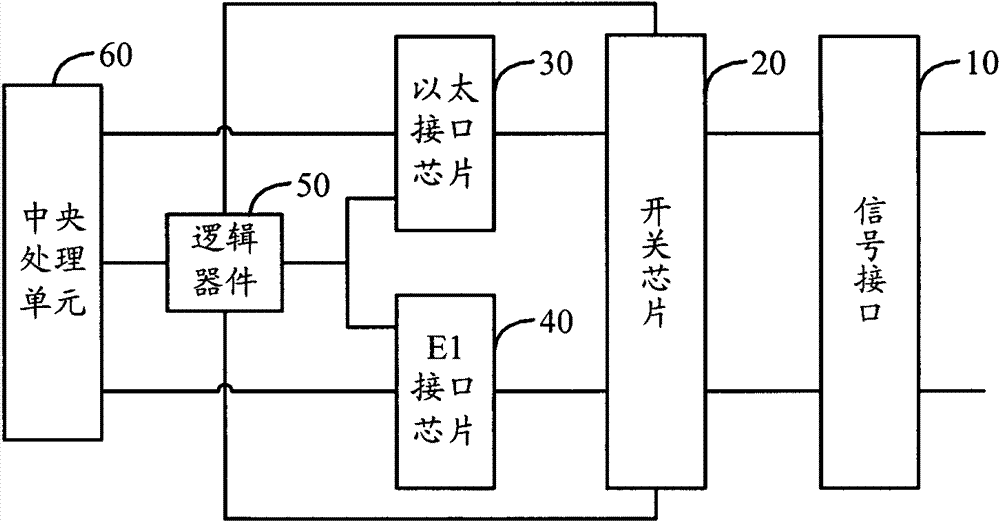
[0028] The communication interface multiplexing device provided by Embodiment 1 of the present invention can be set in any network equipment such as routers, switches, connectors, etc. that need to be provided with Ethernet interfaces and E1 interfaces, such as figure 1 As shown, the device includes: a signal interface 10 , a switch chip 20 , an Ethernet interface chip 30 , an E1 interface chip 40 and a logic device 50 .

[0029] The signal interface 10 is provided with Ethernet interface pins and E1 interface pins, that is, it can be connected with the Ethernet interface or the E1 interface.

[0030] The switch chip 20 can control the connection between the Ethernet interface chip 30 and the signal interface 10 , and control the connection between the E1 interface chip and the signal interface 10 .

[0031] The Ethernet interface chip 30 is connected to the Ethernet interface pin on the signal interface 10 through the switch chip 20, and is used to detect whether the connecte...

Embodiment 2

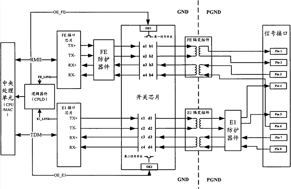
[0048] The communication interface multiplexing device provided by Embodiment 2 of the present invention, such as image 3 As shown, the device includes a signal interface, a switch chip, an Ethernet interface chip (FE PHY), an E1 interface chip (E1PHY), a logic device and a central processing unit.

[0049] Preferably, the device also includes an ether isolation subassembly and an E1 isolation subassembly.

[0050] More preferably, the device may further include an ether protection device and / or an E1 protection device.

[0051] Among them, the central processing unit and the Ethernet interface chip form an Ethernet signal path through the switch chip and the signal interface, specifically including:

[0052] The signal interface can be RJ45 interface or other Ethernet interface. Taking RJ45 interface as an example, there are 8 interface pins including Pin1, Pin2, Pin3, Pin4, Pin5, Pin6, Pin7, and Pin8. Among them, Pin1, Pin2, Pin3, and Pin6 are used for As the Ethernet int...


PUM


Abstract

The invention discloses communication interface multiplexing method, device and network equipment. The communication interface multiplexing device comprises a signal interface, a switch chip, an Ethernet interface chip, an E1 chip and a logic device, wherein the signal interface is provided with an Ethernet interface pin and an E1 interface pin; when the Ethernet interface chip detects that a connected peer end is the Ethernet interface, the logic device is used for controlling the switch chip to maintain that the Ethernet interface chip and the Ethernet interface pin on the signal interface are connected and disconnect the E1 interface chip and E1 interface pin on the signal interface; when the E1 interface chip detects that the connected peer end is the E1 interface, the switch chip is controlled to maintain that the E1 interface chip and the E1 interface pin on the signal interface are connected and disconnect the Ethernet interface chip and the Ethernet interface pin on the signalinterface. The device can realize the multiplexing of the Ethernet interface and the E1 interface, thereby avoiding the waste of interface resource, and saving panel space and equipment cost input.

Description

technical field [0001] The invention relates to the field of computer technology, in particular to a communication interface multiplexing method, device and network equipment. Background technique [0002] At present, due to the development of Ethernet is becoming more and more popular, the density of Ethernet ports on routers is becoming higher and higher, and the trend of convergence of Ethernet and routing is getting stronger and stronger, especially many low-end routers integrate high-density Fast Ethernet (Fast Ethernet, FE) interface. [0003] On the other hand, as the E1 interface of the WAN (European 30-channel pulse code modulation PCM, referred to as E1), due to its long history of application and development in China, many devices still retain the access method using the E1 interface, and because The initial equipment investment is relatively high, and it is inconvenient to replace. Therefore, in order to be able to interconnect with the early equipment, the E1 i...

Claims


Application Information

Patent Timeline
Patent Type & Authority Patents(China)
IPC IPC(8): H04L12/02
Inventor 肖群刘治毅
Owner BEIJING XINWANG RUIJIE NETWORK TECH CO LTD
Why Eureka
Try Eureka