Optical fiber illumination system with optical feedback return circuit

A technology of optical fiber lighting and optical feedback, which is applied to the light guide, lighting device, lighting and heating equipment of the lighting system, etc., can solve the problems that the complete separation of photoelectric and optical fiber lighting cannot be realized, so as to improve the utilization rate of light source, avoid resource idleness, The effect of safe and reliable lighting requirements

Active Publication Date: 2010-06-30
OCEANS KING LIGHTING SCI&TECH CO LTD +1
View PDF0 Cites 17 Cited by
  • Summary
  • Abstract
  • Description
  • Claims
  • Application Information

AI Technical Summary

Problems solved by technology

[0005] The technical problem to be solved by the present invention is to provide a fiber optic lighting system with an optical feedback loop that can solve the defect that the above-mentioned electric control switch in the prior art cannot realize the complete separation of photoelectricity and optical fiber lighting

Method used


Image

  • Optical fiber illumination system with optical feedback return circuit
  • Optical fiber illumination system with optical feedback return circuit
  • Optical fiber illumination system with optical feedback return circuit

Examples


Embodiment Construction

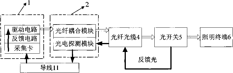
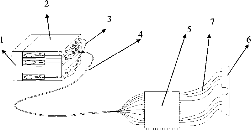
[0023] refer to figure 1 , the driving circuit is connected with the fiber coupling module, drives the LED in the fiber coupling module to emit light, the light enters the optical fiber cable 4 from the output end of the fiber coupling module through coupling, the optical fiber cable 4 sends the light into the optical switch 5, and part of the light passes through the optical switch 5 Entering the lighting terminal 6 to generate lighting, another part of the light becomes feedback light and returns to the optical fiber cable for transmission, and is sent to the photoelectric detection module. The feedback light signal is converted into an electrical signal, and finally sent to the acquisition card through the wire 11. The acquisition card transmits the converted electrical signal to the feedback circuit, and the feedback circuit controls the driving circuit to adjust the power after the feedback circuit responds, thereby changing the luminous power of the entire circuit to ensu...


PUM


Abstract

The invention relates to an optical fiber illumination system with an optical feedback return circuit, comprising a driving circuit, an optical fiber coupling module which is connected with the driving circuit, an illumination terminal (6), and an optical fiber cable (4) which is connected with the optical fiber coupling module and the illumination terminal (6) and is composed of a plurality of optical fibers (14), the optical fiber illumination system with the optical feedback return circuit also comprises a feedback circuit which is connected with the driving circuit, a collecting card which is connected with the feedback circuit and a photoelectricity detecting module of which one end is connected with the collecting card and the other end is connected with the input end of the optical fiber cable (4), and a photoswitch (5) is arranged between the output end of the optical fiber cable (4) and the illumination terminal (6). Feedback light is generated by the photoswitch and is converted into electric signals through the photoelectricity detecting module and then enters the feedback circuit after being collected by the collecting card, light source power is adjusted by the feedback circuit to realize the adjustment of the illumination terminal. The optical fiber lighting system in the invention has complete photoelectricity separating characteristic and can provide safe and reliable optical fiber illumination in the occasion with specific requirements.

Description

technical field [0001] The present invention relates to a fiber optic lighting system, and more particularly, to a fiber optic lighting system with an optical feedback loop. Background technique [0002] As a new lighting method, fiber optic lighting has been widely used in large-scale entertainment, office, stadium, factory and other areas. It has many characteristics that existing lighting methods do not have, such as: the emitted light has no ultraviolet and It is suitable for special lighting such as cultural relic lighting, etc.; it is not subject to electromagnetic interference and can be used in special places with electromagnetic shielding requirements such as nuclear magnetic resonance rooms. [0003] In addition, the biggest advantage of optical fiber lighting is that the light propagates through the optical fiber to the lighting place with a certain distance from the light source, so it has the characteristics of photoelectric separation, especially suitable for u...

Claims


Application Information

Patent Timeline
Patent Type & Authority Applications(China)
IPC IPC(8): F21V8/00F21V23/04F21V5/04F21V29/00F21V7/00H05B37/02F21Y101/02F21V29/50
Inventor 周明杰王省伟
Owner OCEANS KING LIGHTING SCI&TECH CO LTD
Why Eureka
Try Eureka