Electronic system and charging controller circuit thereof

a charging controller and electronic system technology, applied in the field of electronic systems and the charging controller circuit thereof, can solve the problems of redundancy and idle, not all pins are used in the interface, etc., and achieve the effect of improving the interface use ratio

Inactive Publication Date: 2019-01-10
ECOFLOW TECH LTD
View PDF1 Cites 1 Cited by
  • Summary
  • Abstract
  • Description
  • Claims
  • Application Information

AI Technical Summary

Benefits of technology

[0004]Accordingly, it is necessary to provide a charging controller circuit and an electronic system with improved interface use ratio.

Problems solved by technology

However, when a USB interface is implementing a certain function signal, not all pins are used in the interface.
Therefore, there are redundancy and idling.

Method used


Image

  • Electronic system and charging controller circuit thereof
  • Electronic system and charging controller circuit thereof
  • Electronic system and charging controller circuit thereof

Examples


Embodiment Construction

[0013]The present disclosure will be described in details in combination with the accompanying drawings and embodiments such that the purpose, technical solution and advantages of the present disclosure will be more apparent. It should be understood that the particular embodiments are described for the purpose of illustrating as opposed to restricting the present invention.

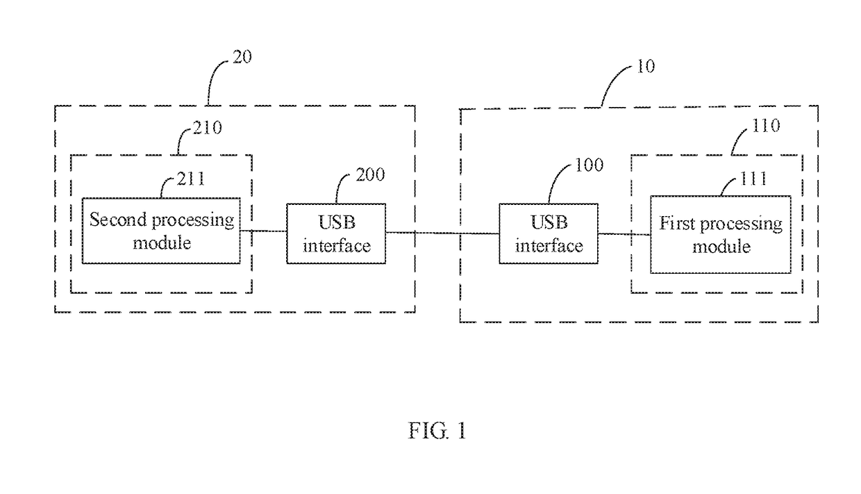
[0014]As illustrated in FIG. 1, a charging controller circuit according to an embodiment includes a first USB interface controller circuit 110 and a second USB interface controller circuit 210. The first USB interface controller circuit 110 is used in the charger device 10 and configured to control the USB interface 100 thereof. The second USB interface controller circuit 210 is used in the device to be charged 20 to control the USB interface 200 thereof.

[0015]The USB interface 100 of the charger device 10 includes a first pin and a second pin. The USB interface 200 of the charger device 20 includes a third pin an...


PUM


Abstract

This disclosure relates to electronic technologies, and in particular relates to A charging controller circuit comprising: a first USB interface controller circuit used in a charger device and configured to control a USB interface of the charger device; and a second USB interface controller circuit used in a device to be charged and configured to control a USB interface of the device to be charged; the first USB interface controller circuit comprises a first processing module; the second USB interface controller circuit comprises a second processing module; the second processing module is configured to transmit a second function signal between the charger device and the device to be charged.

Description

CROSS REFERENCE TO RELATED APPLICATION[0001]This application claims priority to Chinese Patent Application No. 201710544134.3, entitled “ELECTRONIC SYSTEM AND CHARGING CONTROLLER CIRCUIT THEREOF ” filed on Jul. 5, 2017, the content of which is expressly incorporated by reference herein in its entirety.FIELD OF THE INVENTION[0002]This disclosure relates to electronic technologies, and in particular relates to an electronic system and the charging controller circuit thereof.BACKGROUND OF THE INVENTION[0003]To effect the transmission of various function signals such as a discharging function signal, a communication function signal, a video function signal and other private communication signals and so on, a regular electronic device typically needs to be configured with several interfaces. However, when a USB interface is implementing a certain function signal, not all pins are used in the interface. Such as in an ordinary charger, only the VBUS / GND pins of the interface are used for t...

Claims


Application Information

Patent Timeline
Patent Type & Authority Applications(United States)
IPC IPC(8): G06F13/38G06F13/42G06F13/40
CPCG06F13/385G06F2213/0042G06F13/4068G06F13/4286H02J7/0077H02J7/00
Inventor MA, MINGZEZHENG, FAN
Owner ECOFLOW TECH LTD
Why Eureka
Try Eureka