Medical device illumination device

A technology for lighting equipment and medical equipment, applied in medical lighting, mechanical equipment, lighting devices, etc., can solve the problems of energy-saving use of lighting equipment, energy-saving lighting, low layout power, etc., to facilitate disassembly and improve practicability , to avoid the effect of stopping the light

Inactive Publication Date: 2018-12-18
DONGGUAN SONGYAN ZHIDA IND DESIGN CO LTD
View PDF1 Cites 1 Cited by
  • Summary
  • Abstract
  • Description
  • Claims
  • Application Information

AI Technical Summary

Problems solved by technology

[0002] Medical equipment lighting equipment is a device that provides light to medical places. The shadowless lamp can avoid shadows from the backlight, thereby effectively improving the lighting effect. However, it cannot deal with some emergencies, such as power outages and skipping. Moreover, the effect of energy-saving use of lighting equipment cannot be achieved, and it is easy to cause waste of resources.
[0003] The Chinese patent with the authorized notification number CN102537790A discloses a LED shadowless lamp, which includes a circular lamp housing and an LED lamp board installed in the lamp housing. By arranging the LED lamp board with low power, the color temperature, illuminance, and color rendering index are all achieved. The LED light set stipulated in this industry standard makes the manufacturing cost low, but it cannot perform energy-saving lighting, causing unnecessary waste of energy

Method used


Image

  • Medical device illumination device
  • Medical device illumination device
  • Medical device illumination device

Examples


Embodiment Construction

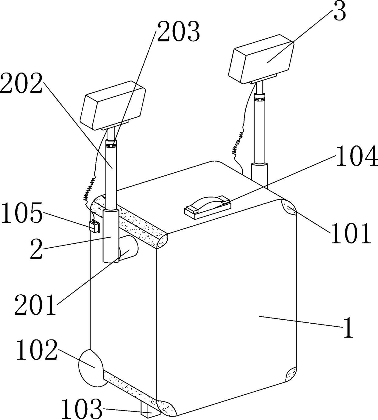
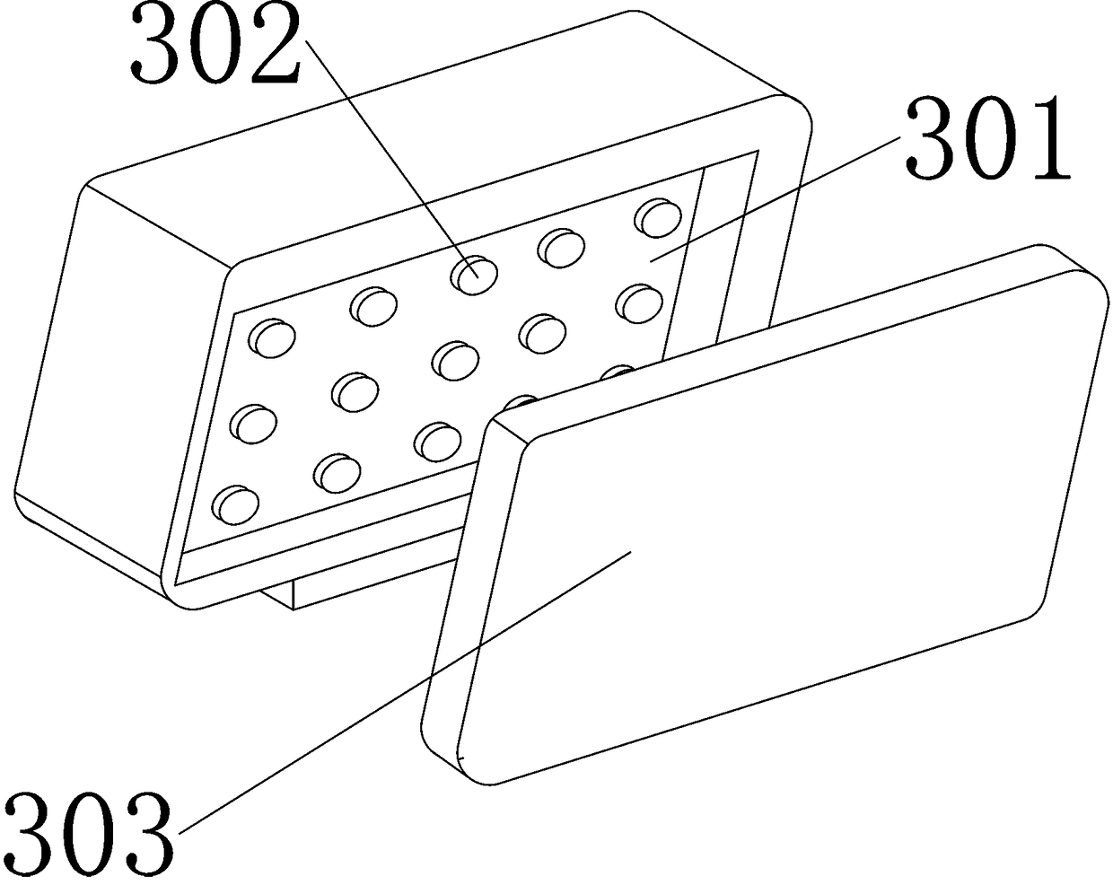
[0033] A lighting device for medical equipment, such as figure 1 As shown, the outer surface of the casing 1 is fixedly connected with a metal wrapping angle 101, and the metal wrapping angle 101 is arranged around the casing 1, which can protect the casing 1 from being damaged, and the scroll wheel movably connected to the outer surface of the bottom of the casing 1 102, in order to enable the casing 1 to move, the bottom outer surface of the casing 1 is fixedly connected with a base 103, and the base 103 and the rolling wheels 102 are on the same horizontal line, so as to support the casing 1 and prevent the casing 1 from sliding The handle 104 fixedly connected to the outer surface of the upper end of the casing 1 is used to facilitate the handling of the casing 1. The left side of the casing 1 is connected with a plug connector 105, and the plug connector 105 is connected to the lampshade 3 through an elastic wire to make the photosensitive shadowless lamp 302 is powered o...


PUM


Abstract

The invention discloses a medical device illumination device and belongs to the field of illumination equipment. According to the technical scheme, the medical device illumination device comprises a machine shell and lamp covers; the machine shell comprises a rechargeable battery bin; the rechargeable battery bin is fixedly connected to the inner bottom surface of the machine shell; each lamp cover comprises a photosensitive shadowless lamp which is fixedly connected to the inner rear surface of the lamp cover; the rear side of the machine shell is fixedly connected with a cover plate; connecting rods are connected to the left side and the right side of the machine shell in a penetrating manner; the outer surfaces of the upper ends of the connecting rods are fixedly connected with the lampcovers; metal wrap angles are fixedly connected to the outer surface of the machine shell; and the metal wrap angles are arranged on the periphery of the machine shell. Illumination intensity of theexternal environment can be automatically sensed through the photosensitive shadowless lamps, and therefore the illumination intensity of the lamps can be changed properly, and the energy conservationand environment friendly effects can be achieved; and heat dissipation holes are evenly distributed in the cover plate so that heat generated by work of the rechargeable battery bin can be dissipated, the working temperature in the machine shell can be reduced, and therefore the effect of prolonging the service life of the rechargeable battery bin is prolonged.

Description

technical field [0001] The invention relates to the field of lighting equipment, in particular to a lighting equipment for medical equipment. Background technique [0002] Medical equipment lighting equipment is a device that provides light to medical places. Shadowless lights can avoid shadows from the backlight, thereby effectively improving the lighting effect. However, it cannot deal with some emergencies, such as power outages and skipping. Moreover, the effect of energy-saving use of lighting equipment cannot be achieved, and it is easy to cause waste of resources. [0003] The Chinese patent with the authorized notification number CN102537790A discloses an LED shadowless lamp, which includes a circular lamp housing and an LED lamp board installed in the lamp housing. By arranging the LED lamp board with low power, the color temperature, illuminance, and color rendering index are all achieved. The LED lamp set specified in this industry standard makes the manufacturin...

Claims


Application Information

Patent Timeline
Patent Type & Authority Applications(China)
IPC IPC(8): F21S9/02F21V21/06F21V21/22F21V21/30F21V23/04F21V29/83F21V3/00F21W131/20
CPCF21S9/022F21V3/00F21V21/06F21V21/22F21V21/30F21V23/0464F21V29/83F21W2131/20
Inventor 彭曙光
Owner DONGGUAN SONGYAN ZHIDA IND DESIGN CO LTD
Why Eureka
Try Eureka