
Visual training instrument

A training instrument and vision technology, applied in the field of vision training instrument, can solve the problems of large differences in binocular training, limited training effect and recovery effect, and achieve the effects of increasing interest and education, improving effect, and improving applicability

Pending Publication Date: 2021-11-12
SUZHOU XUANJIA OPTICS & ELECTRONICS TECH CO LTD
View PDF1 Cites 2 Cited by
  • Summary
  • Abstract
  • Description
  • Claims
  • Application Information

AI Technical Summary

Problems solved by technology

[0005] Aiming at the deficiencies of the prior art, the present invention provides a vision training instrument, which solves the problems of large differences in binocular training and limited training and recovery effects

Method used


Image

  • Visual training instrument
  • Visual training instrument
  • Visual training instrument

Examples


Embodiment 1

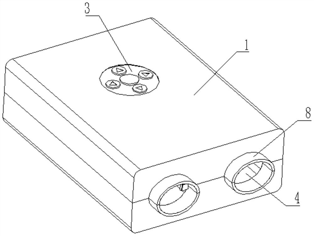
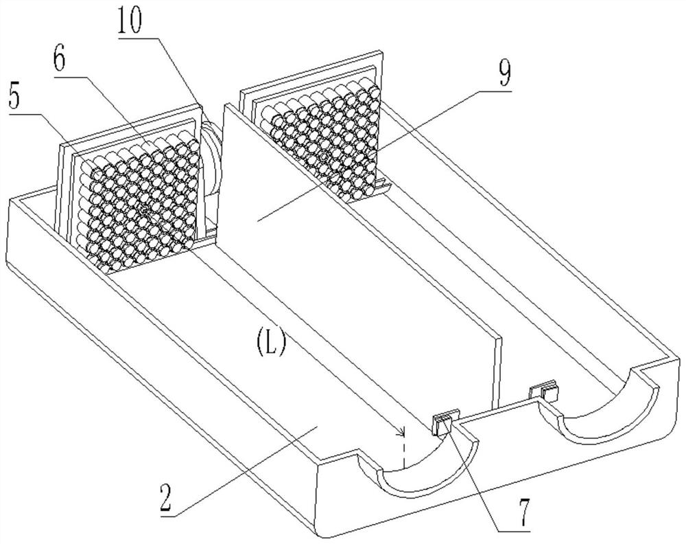
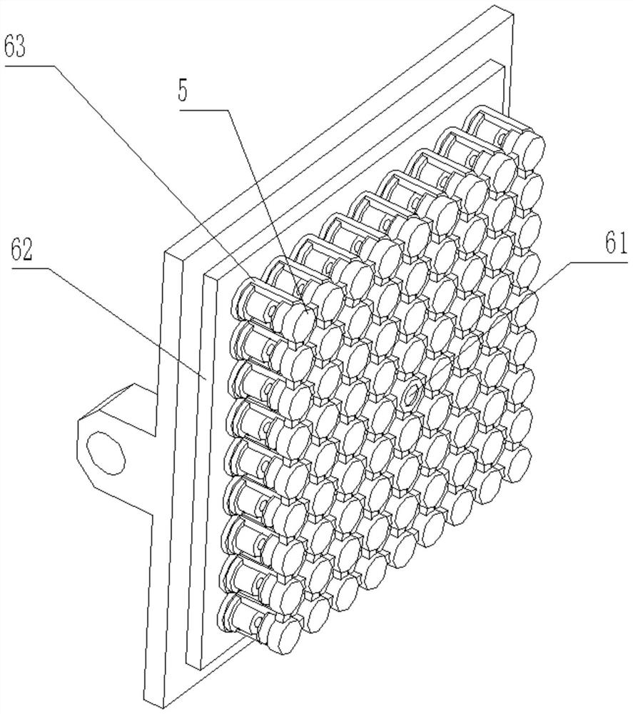
[0054] see Figure 1-11 , a vision training instrument, comprising a housing 1, the front of the housing 1 is provided with a viewing hole 4, the inside of the housing 1 is provided with a cavity 2, and the housing 1 is provided with a light-emitting device 6, the light-emitting device 6 is used to The light source is emitted, and the light-emitting device 6 is provided with an optical wedge device 5; the optical wedge device 5 includes a plurality of deflection lenses 51, the deflection lenses 51 deflect light rays, and the plurality of deflection lenses 51 are connected to each other through a connecting piece 52; The light emitting device 6 includes a circuit board 62, the circuit board 62 is connected with a second laser generator 61 for positioning and several first laser generators 63 for training, and several first laser generators 63 are arranged on the second At the periphery of the laser generator 61, through the beam deflection function of several arrayed deflection...

Embodiment 2

[0082] see Figure 4-8 , Figure 8 The dotted line in the middle of the eye is the irradiation area of ​​the laser. The detection device 7 is arranged in the housing 1, and the detection device 7 is used to detect the light source reflected by the sclera. The detection device 7 includes a control circuit board 73, a photoelectric sensor 72, and a control circuit. The board 73 is connected to the inner wall of the casing 1, and the photoelectric sensor 72 is arranged on the circuit board 73. When the light source emitted by the array light source illuminates the eyes, the light projected on the cornea enters the fundus through the pupil, and is projected to the edge of the cornea and the inner side of the eye. The light on the sclera is reflected, and the overall detection device 7 can detect the intensity of the reflected light at the edge of the cornea in real time, and monitor the position of the user's eyeball in real time through the intensity of the reflected light to det...


PUM


Abstract

The invention relates to the technical field of medical equipment, and discloses a visual training instrument which comprises a shell, wherein a sight hole is arranged on the front part of the shell; a containing cavity is arranged in the shell; a light-emitting device is arranged in the shell and used for emitting a light source; deflection lenses deflect light rays to form the deflection angle and the rotation angle of the light rays; and a plurality of deflection lenses are mutually connected through connecting pieces. According to the visual training instrument, through an arranged optical wedge component, laser emitted by laser light sources arranged in a matrix mode can penetrate through the pupils to irradiate eye grounds of the human eyes, through two sets of identical symmetrical structure shapes, the training environments of the eyes can be basically the same, a recovery difference caused by the recovery environments is reduced, and a visual training effect is improved. Array light source modules can change the illumination intensity of the array light source modules by changing the number of the lightened laser light sources, and a training effect is adjusted.

Description

technical field [0001] The invention relates to the technical field of medical equipment, in particular to a vision training instrument. Background technique [0002] Eyes are the most important organ in human senses. About 80% of the knowledge and memory in the brain are acquired through the eyes. , the number of people with vision problems is increasing, which brings great inconvenience to the lives of many people. [0003] The applicant retrieved a large number of patent documents on the patent network during the conception process. For example, Chinese Patent Publication No. CN201611078159.0 discloses "light wave traction vision training instrument with lens structure", which includes a housing and a circuit board arranged in the housing. , the circuit board is connected to a pair of light sources on the side close to the eyes, and the other side of the circuit board is connected to a power supply; a pair of lenses are also arranged in the housing, and one side of the l...

Claims


Application Information

Patent Timeline
Patent Type & Authority Applications(China)
IPC IPC(8): A61H5/00
CPCA61H5/00A61H2205/024
Inventor 李培文卢鹏
Owner SUZHOU XUANJIA OPTICS & ELECTRONICS TECH CO LTD
Learn More