
New isolated cable TV connector
A technology for cable TV and connectors, which is applied in the field of new isolated cable TV connectors, can solve the problem of low working stability of connectors, and achieve the effect of stable contact
- Summary
- Abstract
- Description
- Claims
- Application Information
AI Technical Summary
Problems solved by technology
Method used
Image

Examples
Embodiment 1
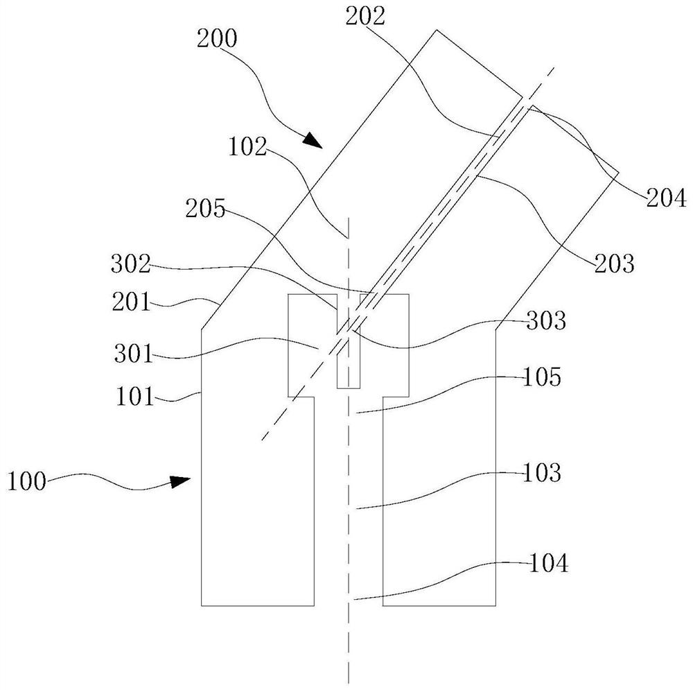
[0023] Please refer to figure 1 The TV connector includes a plug part 100 and a connection part 200, the end of the plug part 100 has a plug end 101, and the end of the connection part 200 has a connection end 201 corresponding to the plug end 101, and the plug part 100 and the connection part 200 are connected , Can be split connection or integral molding, preferably integral molding. The plug part 100 forms a plug channel 103 along its first central axis 102. Both ends of the plug channel 103 are the plug inlet 104, the plug outlet 105, and the wiring part 200. A wiring channel 203 is formed along its second central axis 202. The two ends of the wiring channel 203 are respectively a wiring inlet 204 and a wiring outlet 205. The plug channel 103 communicates with the wiring channel 203, and the plug channel 103 communicates with the wiring channel 203 to form a cavity 301. The upper end of the cavity 301 has a connecting terminal 302 extending downward. The connecting terminal ...
Embodiment 2
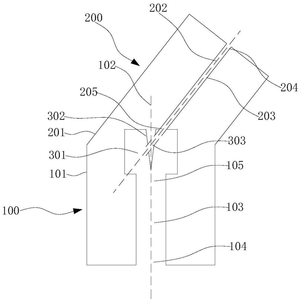
[0026] Please refer to figure 2 The difference between the second embodiment and the first embodiment is that the connecting terminal 302 in the first embodiment is cylindrical, and the connecting terminal 302 in the second embodiment is a cone with a downward taper angle.
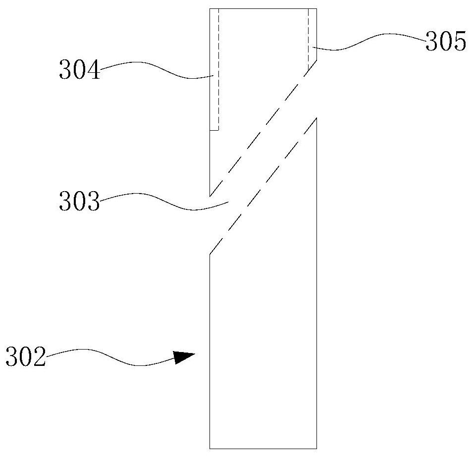
[0027] Please refer to image 3 , Figure 4 In the vertical direction, the side surface of the cylindrical connecting terminal 302 has a wire inlet groove and a wire outlet groove corresponding to the wire inlet hole and the wire outlet hole of the through hole 303, respectively. The wire inlet and outlet grooves can be folded into the wire inlet groove 305 and the wire outlet groove 304 when the signal wire is bent to prevent the signal wire from sliding along the side wall of the terminal 302 at both ends of the through hole 303. Preferably, the cross sections of the wire inlet groove 305 and the wire outlet groove 304 are rectangular, semicircular or arc-shaped. In the second embodiment, the conical conn...
PUM
 Abstract
Description
Claims
Application Information