Rapid drying equipment in textile fabric production process

A production process, fast drying technology, applied in drying, dryer, lighting and heating equipment, etc., can solve the problems affecting the appearance quality of textile cloth, single function, deformation of textile cloth and so on

Inactive Publication Date: 2019-01-08
武汉中智德远科技开发有限公司
View PDF4 Cites 3 Cited by
  • Summary
  • Abstract
  • Description
  • Claims
  • Application Information

AI Technical Summary

Problems solved by technology

Textile fabrics are processed using dryers for drying. However, the existing dryers on the market have a single function when drying textile fabrics, so it takes a long time for the dryer to dry textile fabrics. At the same time, drying t

Method used


Image

  • Rapid drying equipment in textile fabric production process
  • Rapid drying equipment in textile fabric production process
  • Rapid drying equipment in textile fabric production process

Examples


Embodiment 1

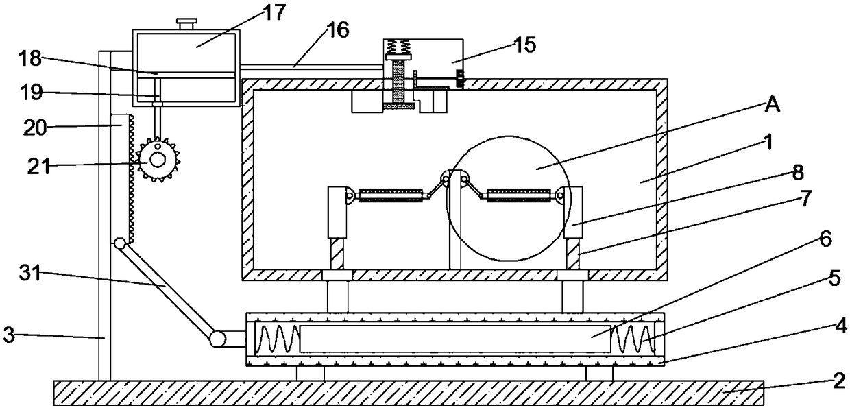
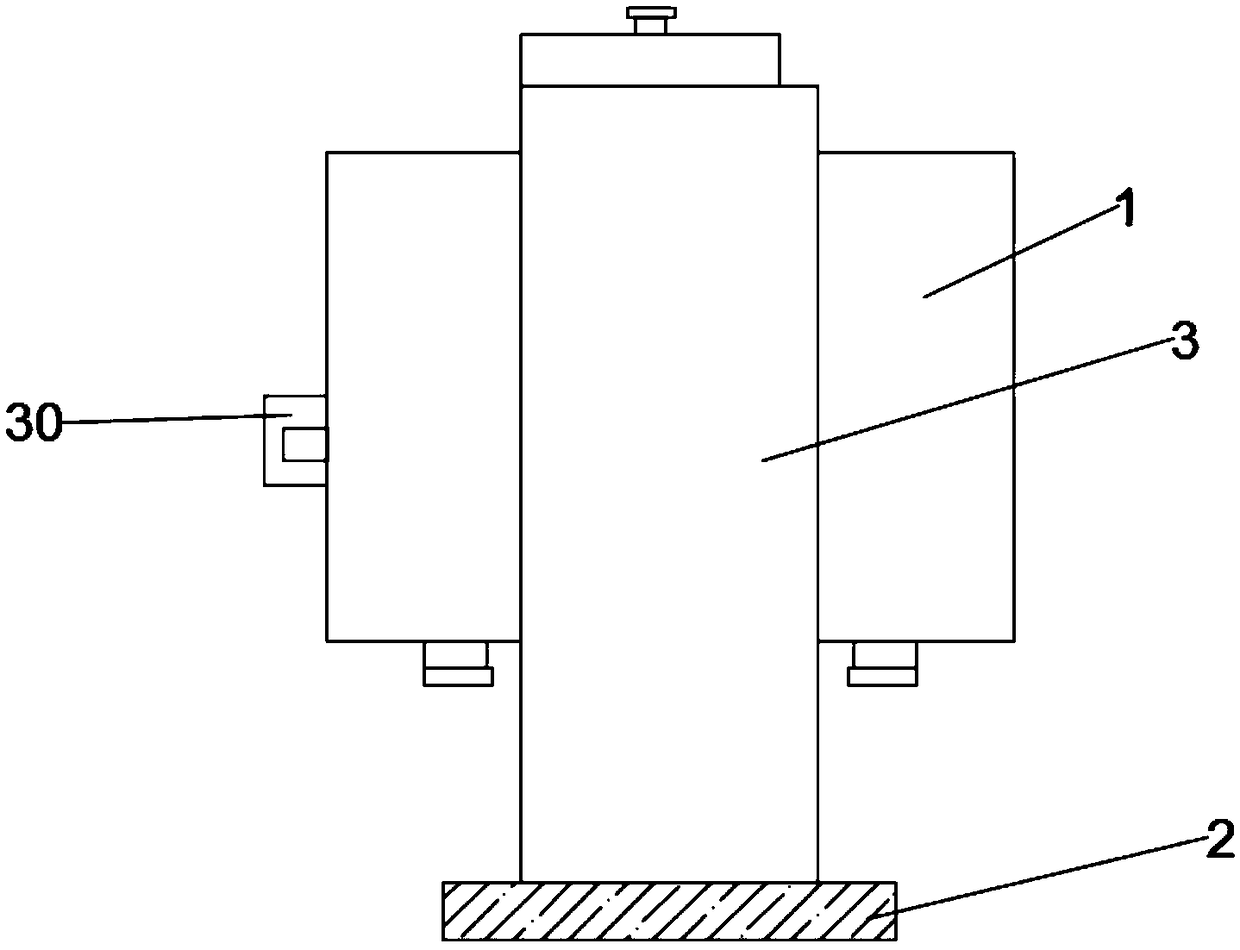
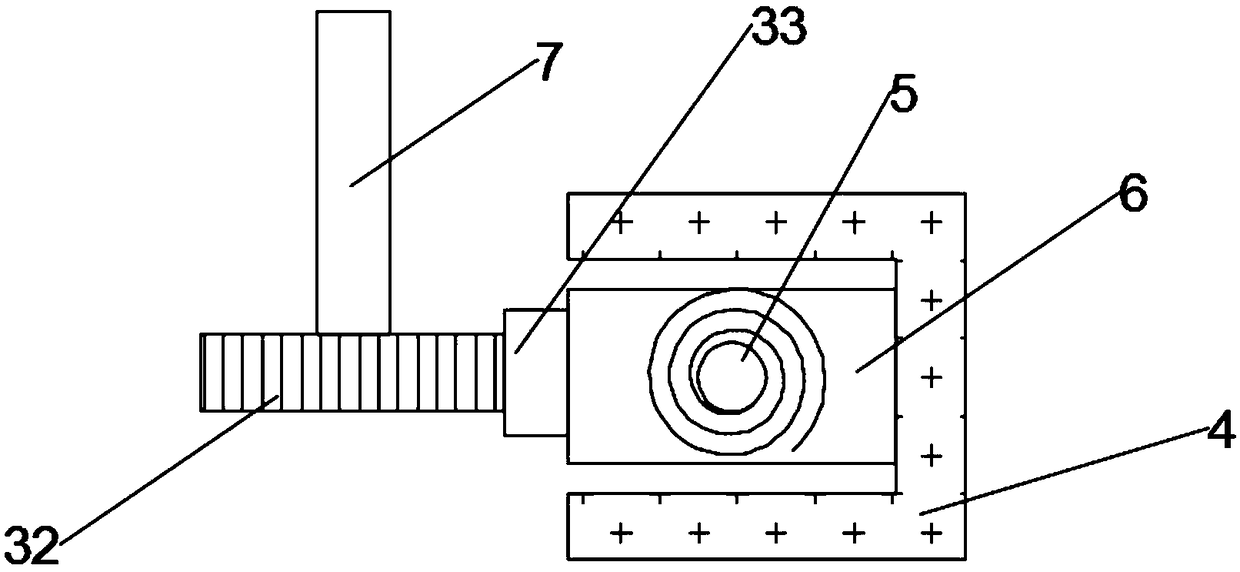
[0021] see Figure 1~4 , in an embodiment of the present invention, a kind of rapid drying equipment in the production process of textile fabrics, including a drying box 1, a supporting base 2, a supporting column 3, a horizontal chute 4 and a vapor compression chamber 17, after the drying box 1 The entrance 30 is set at the middle position of the side, the air outlets are set on both sides of the bottom surface of the drying box 1, two placement plates 10 are arranged inside the drying box 1, and the upper left side of the drying box 1 is fixedly connected to the vapor compression chamber 17. The left side of the vapor compression chamber 17 is fixed on the support column 3, and the lower end of the support column 3 is fixed with a welding support base 2, and the support base 2 is horizontally arranged under the drying box 1, and the drying box A horizontal chute 4 is arranged in parallel between 1 and the support base 2;

[0022] The right side wall of the support column 3 ...

Embodiment 2

[0027] Such as Figure 5 As shown, in this embodiment, a steam discharge device 15 is provided between the guide pipe 16 and the inner cavity of the drying box 1, and the left side wall of the steam discharge device 15 communicates with the guide pipe 16. Two second buffer springs 25 are arranged on the left side of the inner cavity top of the steam discharge device 15, the upper end of the second buffer spring 25 is fixedly welded to the upper wall of the steam discharge device 15, and the lower end of the second buffer spring 25 is fixedly welded to the first connection Rod 22, the first connecting rod 22 is vertically arranged, the first diversion opening 24 is arranged at a corresponding position below the first connecting rod 22, and the lower end of the first connecting rod 22 is fixedly connected to the sealing plug 23, the A gap is set between the sealing plug 23 and the right side wall of the first diversion opening 24, and when the steam flow rate is small, the steam...


PUM


Abstract

The invention discloses rapid drying equipment in a textile fabric production process. The rapid drying equipment comprises a drying box, a supporting base, a supporting stand column, a horizontal sliding groove and a steam compression cavity, wherein an inlet is formed in the middle of the rear side of the drying box, air outlets are arranged oppositely on the two sides of the surface of the drying box, and two containing plates are arranged inside the drying box; and the rapid drying equipment is characterized in that the steam compression cavity is fixedly connected to the left upper part of the drying box, the left side of the steam compression cavity is fixed on the supporting stand column, a supporting base is fixedly welded to the lower end of the supporting stand column, the supporting base is horizontally arranged below the drying box, and a horizontal sliding groove is formed between the drying box and the supporting base in parallel. According to the equipment, the design isreasonable, the textile fabric can be quickly dried, so that the textile fabric deformation caused by long-time drying of the textile fabric is avoided; and the equipment has the advantages of beingenergy-saving, and capable of reducing the burden of workers.

Description

technical field [0001] The invention relates to the field of textile processing equipment, in particular to a rapid drying equipment in the production process of textile cloth. Background technique [0002] The dryer has several modes such as belt drying, drum drying, box drying, and tower drying; the heat source includes coal, electricity, gas, etc.; the drying process of materials has hot air flow type and radiation type, etc. , hot air drum drying is that the hot air flow moves forward from the tail, fully contacts with the material, and makes full use of the heat transfer through heat conduction, convection, and radiation; the heat energy is directly transferred to the material, so that the moisture of the material is continuously evaporated in the cylinder, and the material is fed into the cylinder. The air-introduction device at the outlet draws out a large amount of water and wet air to prevent secondary pollution caused by dust discharge; through internal spiral stir...

Claims


Application Information

Patent Timeline
IPC IPC(8): F26B9/08F26B25/00
CPCF26B9/08F26B25/00
Inventor 谢文方
Owner 武汉中智德远科技开发有限公司
Why Eureka
Try Eureka