A controller and control method for reducing energy consumption

A technology of controller and energy consumption, applied in the field of negative pressure system control and automobile negative pressure braking system, can solve the problems of large energy consumption of negative pressure system, and achieve the effect of low cost and simple structure

Active Publication Date: 2020-06-19
滨州高新区国有资本投资运营有限公司
View PDF5 Cites 0 Cited by
  • Summary
  • Abstract
  • Description
  • Claims
  • Application Information

AI Technical Summary

Problems solved by technology

[0006] The present invention mainly aims to solve the problem of large energy consumption in the negative pressure system in the prior art, and provides a controller and a control method for reducing energy consumption

Method used


Image

  • A controller and control method for reducing energy consumption
  • A controller and control method for reducing energy consumption
  • A controller and control method for reducing energy consumption

Examples


Embodiment 1

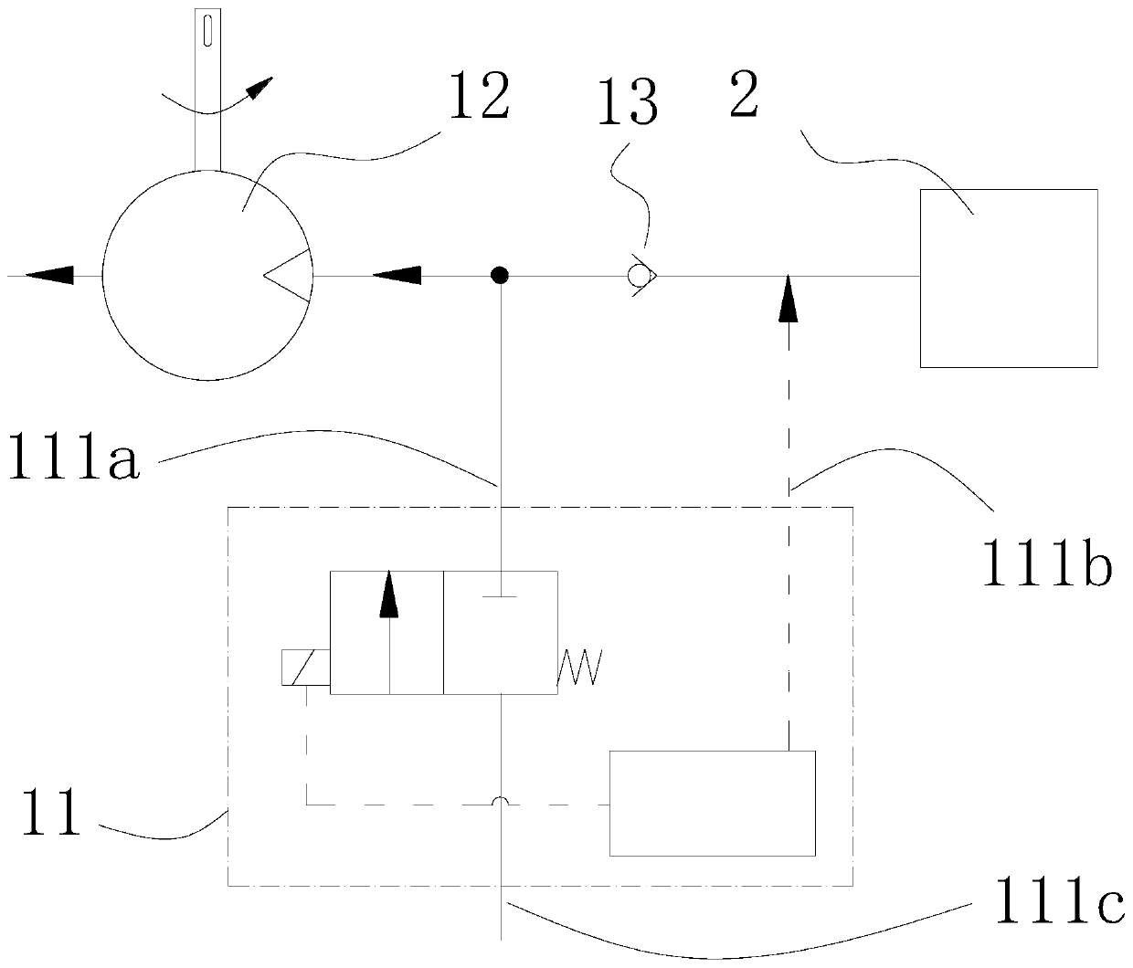
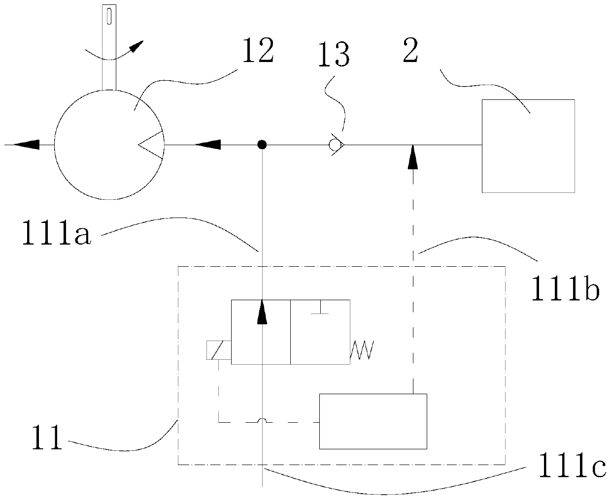
[0075] Such as figure 2 and image 3 As shown, the controller 11 includes an electric valve, a control unit and a pressure sensor. The electric valve has two openings respectively connected to the air outlet 111a and the air inlet 111c. The electric valve is controlled by the control unit and can switch the air outlet 111a and the air inlet. Port 111c is connected and disconnected; further, in order to maintain the safety of the negative pressure system, when the electric valve does not receive a signal or is powered off, the gas outlet 111a and the inlet 111c are in a disconnected state, and the negative pressure pump 12 The negative pressure consumer 2 can be sucked continuously. The air outlet 111 a is connected to the side of the one-way valve facing the negative pressure pump 12 through an air path, wherein the side of the one-way valve facing the negative pressure pump 12 includes a one-way valve, a pipeline and the negative pressure pump 12 . The air inlet 111c leads...

Embodiment 2

[0080] In Embodiment 1, the controller 11 needs to use a pressure sensor to detect the pressure value in the negative pressure consumer 2 through an electrical connection, and can also use a purely mechanical method to detect the pressure value in the negative pressure consumer 2 and control the The communication state of the air port 111a and the air inlet 111c.

[0081] Such as Figure 4 and Figure 5 As shown, the controller 11 has three gas circuit interfaces, which are the air outlet 111a, the air inlet 111c, and the detection port 111b. The communication state between the air outlet 111a and the air inlet 111c is controlled by the pressure state received by the detection port 111b. , when the pressure received by the detection port 111b is less than the set threshold, the gas outlet 111a is connected to the air inlet 111c, and the negative pressure system is in a constant flow state; when the pressure received by the detection port 111b is greater than the set threshold...

Embodiment 3

[0094] In the first embodiment, the first sealing ring 115 a , the second sealing ring 115 b and the third sealing ring 115 c are arranged on the outer surface of the piston 114 , and these sealing rings can also be arranged on the inner surface of the housing 111 .

[0095] Such as Figure 11 to Figure 15 As shown, the controller 11 includes a housing 111 and a piston 114. The outer side of the housing 111 is provided with through holes through the inner and outer walls, which are respectively an air outlet 111a, an air inlet 111c and a detection port 111b. Between the housing 111 and the piston 114 A sealing ring is provided, and the piston 114 slides inside the housing 111; when the pressure of the detection port 111b is greater than the pressure threshold (when the controller 11 is not installed and used, the port is free when the port is connected to the atmosphere), the air outlet 111a, the air inlet 111c and the The detection ports 111b communicate with mutually indepen...


PUM


Abstract

The invention discloses a controller for reducing energy consumption and a control method thereof, belonging to the field of negative pressure system control, in particular to the field of automobilenegative pressure braking system. The controller for reducing energy consumption is used for controlling a negative pressure system composed of a negative pressure pump, a one-way valve and a negativepressure consumer, wherein an air outlet, an air inlet and a detection port are arranged on the outer side of a shell; the air outlet and the air inlet are respectively connected with the two ends ofa hose; a piston is fixedly connected with a pressing block; the support seat is fixedly connected with the shell, and the hose is arranged between the pressing block and the support seat; when the pressure of the detection port is higher than the pressure threshold, the air outlet and the air inlet are communicated with each other separately, and the negative pressure system is in the negative pressure state; and when the pressure of the detection port is lower than the pressure threshold, the negative pressure system is in a constant flow state in the same area where the outlet and inlet are communicated. The controller for reducing energy consumption has low cost and simple structure, and the existing negative pressure system can be directly installed, thus being able to be applied todifferent environmental pressure conditions, so as to realize the negative pressure pump of the negative pressure system to work on demand, and solve the problems in the prior art.

Description

technical field [0001] The invention discloses a controller and a control method for reducing energy consumption, which belong to the field of negative pressure system control, and in particular relate to the field of automobile negative pressure brake systems. Background technique [0002] The structure of the negative pressure system is composed of a negative pressure pump and a negative pressure consumer connected by a pipeline. A one-way valve is set in the middle of the pipeline to reduce the negative pressure fluctuation of the negative pressure consumer. The negative pressure pump is driven by a power source to generate negative pressure. pressure, but the negative pressure consumer does not consume negative pressure energy continuously, and the negative pressure pump continues to run. The high negative pressure in the system will cause a large pressure difference between the inlet and outlet of the pressure pump, and the load of the negative pressure pump It is very ...

Claims


Application Information

Patent Timeline
Patent Type & Authority Patents(China)
IPC IPC(8): B60T13/24B60T13/68B60T17/00
CPCB60T13/241B60T13/683B60T17/00
Inventor 余静远
Owner 滨州高新区国有资本投资运营有限公司
Why Eureka
Try Eureka