Controller and control method
A controller and consumer technology, applied in the direction of brakes, brake components, brake transmission devices, etc., can solve the problem of large energy consumption in negative pressure systems, and achieve the effect of low cost and simple structure
- Summary
- Abstract
- Description
- Claims
- Application Information
AI Technical Summary
Problems solved by technology
Method used
Image
Examples
Embodiment 1
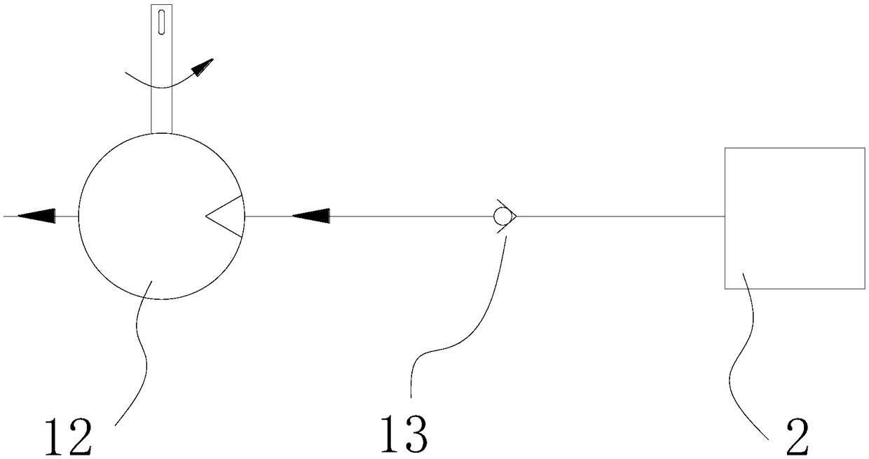
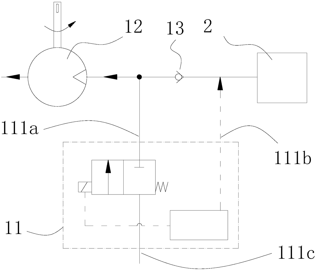
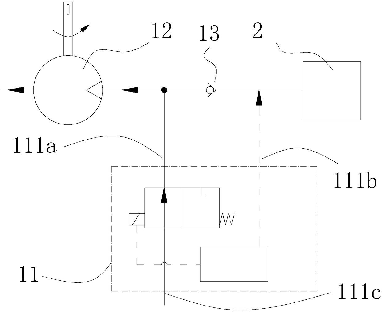
[0075] Such as figure 2 with image 3 As shown, the controller 11 includes an electric valve, a control unit, and a pressure sensor. The electric valve has two openings connected to the air outlet 111a and the air inlet 111c, respectively. The electric valve is controlled by the control unit to switch the air outlet 111a and the air inlet. Port 111c is connected and disconnected; further, in order to maintain the safety of the negative pressure system, when the electric valve does not receive a signal or is powered off, the air outlet 111a and the air inlet 111c are in a non-connected state, and the negative pressure pump 12 can continuously suck the negative pressure consumer 2. The air outlet 111a is connected to the side of the one-way valve facing the negative pressure pump 12 through a gas path, wherein the side of the one-way valve facing the negative pressure pump 12 includes a one-way valve, a pipeline, and the negative pressure pump 12. The air inlet 111c is open to t...
Embodiment 2
[0080] In the first embodiment, the controller 11 needs to use a pressure sensor to detect the pressure value in the negative pressure consumer 2 through an electrical connection. It can also detect the pressure value in the negative pressure consumer 2 in a purely mechanical manner and control the output The communication state of the air port 111a and the air inlet 111c.
[0081] Such as Figure 4 with Figure 5 As shown, the controller 11 has three gas ports, namely the outlet 111a, the inlet 111c, and the detection port 111b. The communication state between the outlet 111a and the inlet 111c is controlled by the pressure state received by the detection port 111b. When the pressure received by the detection port 111b is less than the set threshold, the outlet 111a and the air inlet 111c are connected, and the negative pressure system is in a constant flow state; when the pressure received by the detection port 111b is greater than the set threshold, the outlet 111a and the inle...
Embodiment 3
[0094] In the first embodiment, the first sealing ring 115a, the second sealing ring 115b and the third sealing ring 115c are arranged on the outer surface of the piston 114, and these sealing rings can also be arranged on the inner surface of the housing 111.
[0095] Such as Figure 11 to Figure 15 As shown, the controller 11 includes a housing 111 and a piston 114. The outer side of the housing 111 is provided with through holes penetrating through the inner and outer walls of the air outlet 111a, the air inlet 111c, and the detection port 111b. Between the housing 111 and the piston 114 With a sealing ring, the piston 114 slides inside the housing 111; when the pressure of the detection port 111b is greater than the pressure threshold (when the controller 11 is not installed and used, this port is free when connected to the atmosphere), the air outlet 111a, the air inlet 111c and The detection ports 111b are respectively connected to independent areas, and the negative pressur...
PUM
 Abstract
Description
Claims
Application Information
 - R&D
- Intellectual Property
- Life Sciences
- Materials
- Tech Scout
- Unparalleled Data Quality
- Higher Quality Content
- 60% Fewer Hallucinations
Browse by: Latest US Patents, China's latest patents, Technical Efficacy Thesaurus, Application Domain, Technology Topic, Popular Technical Reports.
© 2025 PatSnap. All rights reserved.Legal|Privacy policy|Modern Slavery Act Transparency Statement|Sitemap|About US| Contact US: help@patsnap.com


