Cooking utensil

A technology for cooking utensils and air intake pipes, which is applied to the covers of cooking utensils, cooking utensils, household utensils, etc., can solve the problems of residues, agglomeration, hanging on the wall, rice and other materials that are difficult to enter into the pot, etc. simple structure

Pending Publication Date: 2019-01-22
FOSHAN SHUNDE MIDEA ELECTRICAL HEATING APPLIANCES MFG CO LTD
View PDF0 Cites 0 Cited by
  • Summary
  • Abstract
  • Description
  • Claims
  • Application Information

AI Technical Summary

Problems solved by technology

[0002] At present, intelligent cooking appliances such as automatic rice cookers have the function of automatically cleaning materials. The materials are washed outside the pot first, and then sent into the inner pot after washing. However, rice and other materials are prone to agglomeration and wall hanging on the surface after washing Phenomenon, making it difficult for rice and other materials to enter the pot and the problem of residue

Method used


Image

  • Cooking utensil
  • Cooking utensil
  • Cooking utensil

Examples


Embodiment 1

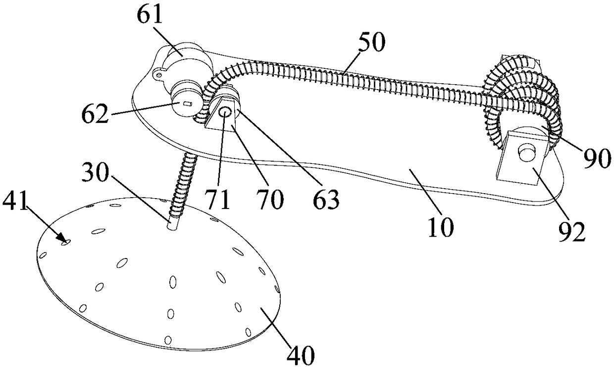
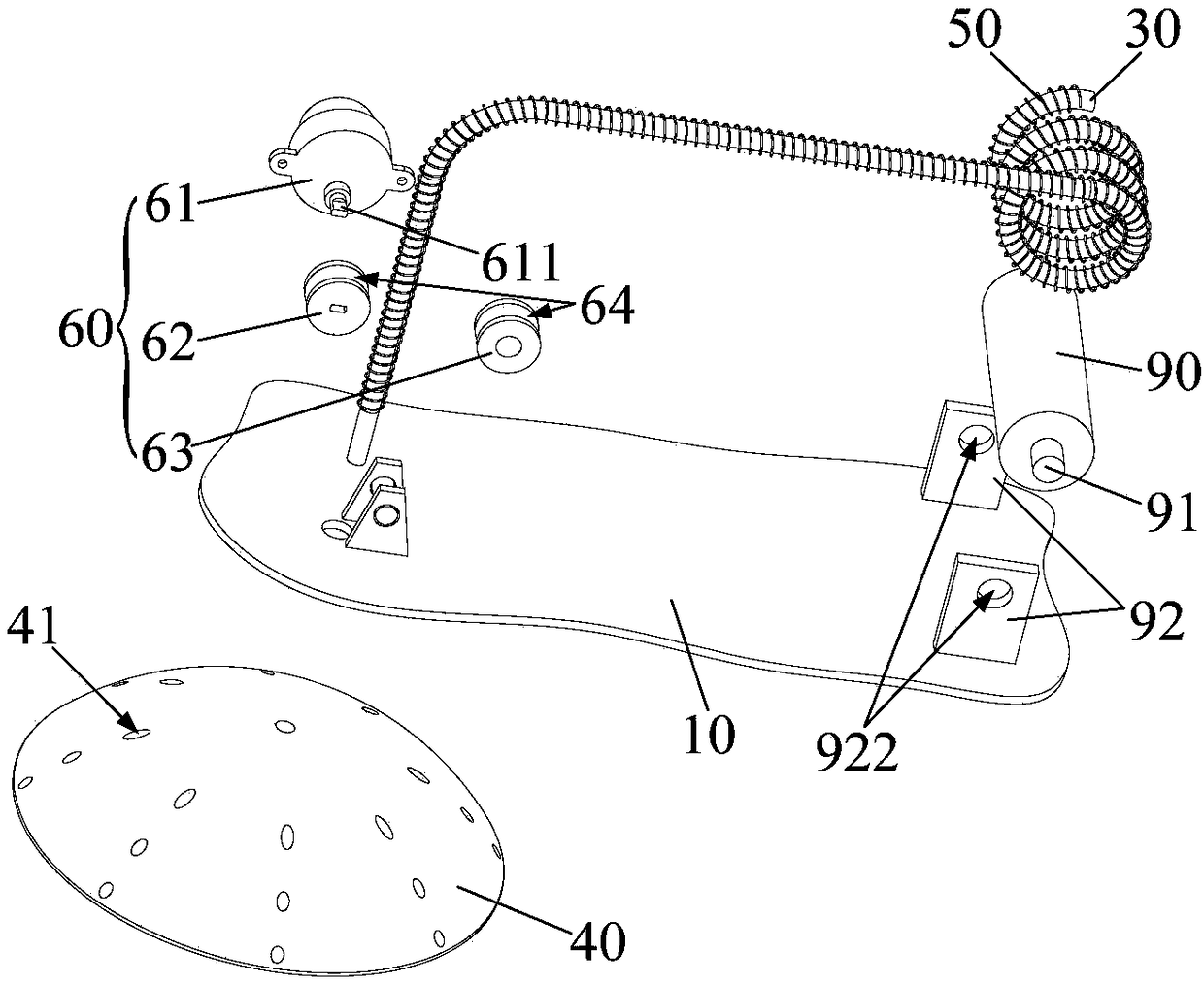
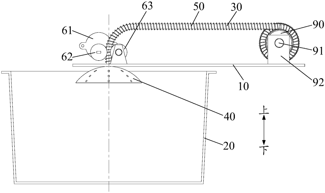
[0086] Embodiment one (as Figure 1 to Figure 5 shown)

[0087] The air intake pipe is a telescopic hollow hose 30, the input end of the air intake pipe is fixed on the upper cover 10, the output end of the air intake pipe runs through the upper cover 10 and communicates with the inner pot 20, and can move to the inner pot under the drive of the telescopic device. The bottom of the pot 20 conveys the air flow.

[0088] The intake pipe is a telescopic hollow hose 30, that is, the intake pipe can undergo axial telescopic deformation to adjust its length, and can undergo radial elastic deformation to adjust its cross-sectional size. In this way, the input end of the intake pipe is fixed. On the upper cover 10, it can ensure its stable cooperation with the air sources such as high-pressure air pumps and fans, and its output end can move up and down in the inner pot 20 under the drive of the telescopic device to ensure the use requirements.

[0089] Further, as Figure 1 to Figu...

Embodiment 2

[0109] The difference from Embodiment 1 is that: the groove wall of the wheel groove 64 is provided with an engaging groove 65 that is compatible with the spring wire of the spring tube 50, such as Figure 9 and Figure 13 As shown, the spring wire is embedded in the engaging groove 65 to engage the spring tube 50 with the groove wall of the wheel groove 64 .

[0110] Directly on the groove wall of the wheel groove 64, an engaging groove 65 that is compatible with the spring wire of the spring tube 50 is provided, then the spring wire can be directly embedded in the engaging groove 65, and then tightly engaged with the groove wall of the wheel groove 64, thereby improving the The occlusion depth further improves the reliability of cooperation between the spring tube 50 and the driving assembly 60 . Of course, in this case, the driving wheel 62 and the driven wheel 63 can also be soft rubber wheels.

[0111] Its working principle is the same as that of Embodiment 1, and will ...

Embodiment 3

[0112] Embodiment three (as Figure 6 to Figure 17 shown)

[0113] On the basis of the second embodiment, further, a sliding hole 72 is opened on the bracket 70, and the wheel shaft 71 is inserted in the sliding hole 72, and can slide back and forth along the sliding hole 72, as Figure 6 to Figure 8 Shown; The floating limit assembly 80 that abuts against the axle 71 is also installed on the bracket 70, as Figure 6 , Figure 7 , Figure 10 , Figure 11 , Figure 12 , Figure 13 , Figure 14 , Figure 15 , Figure 16 and Figure 17 As shown, the floating limit assembly 80 can perform telescopic movement, so that the wheel shaft 71 slides along the sliding hole 72 to adjust the size of the gap, so that the spring tube 50 and the driving wheel 62 are tightly engaged.

[0114] Since the spring tube 50 and the hollow hose 30 are also accompanied by an appropriate amount of change in cross-sectional size when doing telescopic movement, if the gap between the driving whee...


PUM


Abstract

The invention provides a cooking utensil. The cooking utensil comprises an upper cover, an inner pot, an air inlet pipe and a telescopic device, wherein the air inlet pipe is mounted on the upper cover, and the inlet end of the air inlet pipe can be connected with an air source; the telescopic device is mounted on the upper cover, is connected with the outlet end of the air inlet pipe, and can perform telescoping movement between the upper cover and the inner pot, so that the outlet end of the air inlet pipe is driven to move to the bottom of the inner pot for conveying air flow or the air flow delivered by the air inlet pipe is conveyed to the bottom of the inner pot by utilizing an internal channel, thus materials and water generate relative movement under the effect of the air flow, andthen the materials are washed. For the cooking utensil, the materials are directly washed by using water in the inner pot, and thus the problem that the materials have difficulty in entering the potand residues exist when the materials are washed at the outside of the pot is solved; and meanwhile, the air flow conveyed by the air inlet pipe or the telescopic device can rise upwards from the bottom of a mixture of the materials and the water, thus the materials and water in the inner pot are effectively driven to roll, and therefore, an effective stirring effect is achieved.

Description

technical field [0001] The invention relates to the technical field of kitchen appliances, in particular to a cooking utensil. Background technique [0002] At present, intelligent cooking appliances such as automatic rice cookers have the function of automatically cleaning materials. The materials are washed outside the pot first, and then sent to the inner pot after washing. However, rice and other materials are prone to agglomeration and wall hanging after washing. Phenomenon, resulting in rice and other materials are difficult to enter the pot and the problem of residue. Contents of the invention [0003] In order to solve at least one of the above technical problems, the object of the present invention is to provide a cooking utensil. [0004] In order to achieve the above object, the present invention provides a cooking utensil, comprising: an upper cover; an inner pot, located below the upper cover, for carrying water and materials; an air inlet pipe, installed on ...

Claims


Application Information

Patent Timeline
Patent Type & Authority Applications(China)
IPC IPC(8): A47J27/00A47J43/24A47J36/00A47J36/06
CPCA47J27/004A47J36/00A47J36/06A47J43/24
Inventor 潘典国陈炜杰何柏锋周忠宝杨保民康远宁周亚
Owner FOSHAN SHUNDE MIDEA ELECTRICAL HEATING APPLIANCES MFG CO LTD
Why Eureka
Try Eureka