Al technical title is built by PatSnap Al team. It summarizes the technical point description of the patent document.
A stamping machine, intelligent technology, applied in printing, stamping and other directions, can solve the problems of low reliability, low work precision, low work efficiency, etc., to improve the use reliability, high work precision, high work efficiency Effect
Inactive Publication Date: 2019-03-15
虞家俨
View PDF5 Cites 1 Cited by
Summary
Abstract
Description
Claims
Application Information
AI Technical Summary
This helps you quickly interpret patents by identifying the three key elements:
Problems solved by technology
Method used
Benefits of technology
Problems solved by technology
[0002] As we all know, a stamping machine is a device used to perform appropriate casting on related metal profiles so that they can meet the requirements of related use. It is widely used in the field of die-casting of paper and other materials; now Some stamping machines include a body, a connecting frame, a support frame, a seal, a first connecting rod, a second connecting rod and a base plate, and the top and bottom ends of the connecting frame are respectively connected with the bottom end of the body and the top end of the supporting frame, and the base plate is installed At the top of the support frame, the top of the first connecting rod is connected to the bottom of the machine body, the top of the second connecting rod is inserted into the bottom of the first connecting rod, and the first connecting rod is provided with multiple sets of transverse openings and a set of longitudinal openings. Openings, multiple sets of transverse openings are all connected to the longitudinal openings, the second connecting rod is provided with a pull rod, the pull rod protrudes from the longitudinal opening, the seal is installed at the bottom of the second connecting rod, and the bottom of the seal is provided with Groove; when the existing stamping machine is used, the profiles of materials such as cast paper are placed on the top of the bottom plate, and the relevant personnel manually move the pull rod to drive the second connecting rod to drive the seal to move and press the relevant certificate materials and other paper to However, it is found in the use of the existing stamping machine that it requires the user to manually move the stamp to work, the work accuracy is low, the use effect is poor, and the practicability is low; and its work efficiency Low, which brings inconvenience to users, resulting in low reliability of use
Method used
Image
Click on the blue label to locate the original text in one second.
Reading with bidirectional positioning of images and text.
Examples
Embodiment Construction
[0018] The specific implementation manners of the present invention will be further described in detail below in conjunction with the accompanying drawings and embodiments. The following examples are used to illustrate the present invention, but are not intended to limit the scope of the present invention.
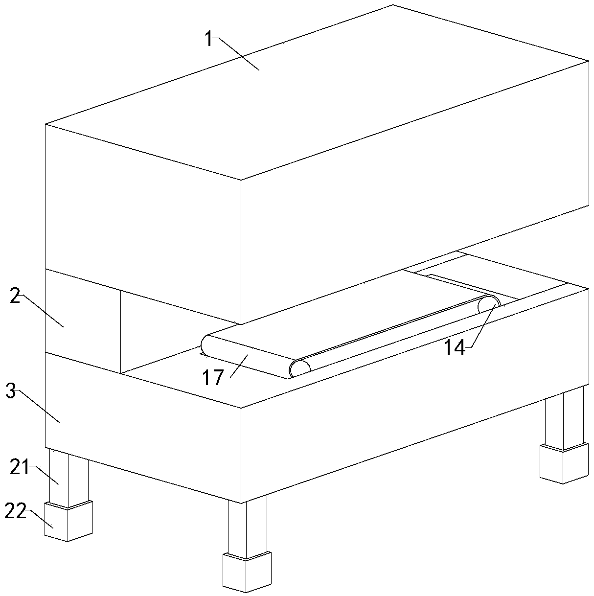
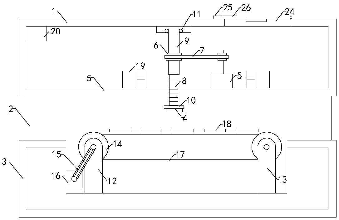
[0019] Such as Figure 1 to Figure 4 As shown, the intelligent stamping machine of the present invention comprises a body 1, a connecting frame 2, a support frame 3 and a seal 4, the top and the bottom of the connecting frame are respectively connected with the bottom end of the body and the top end of the support frame, and the bottom end of the seal is provided with a concave Groove; the body is provided with a working chamber, the bottom of the body is provided with an opening, and the opening communicates with the working chamber, and also includes a servo motor 5, a driving gear, a driven gear 6, a chain 7, a threaded rod 8, a threaded pipe 9 and a connecting plate 10...
PUM
Abstract
The invention relates to the technical field of stationery and sporting goods equipment accessory devices, in particular to an intelligent stamping machine. A stamp can be freely moved for work, the working precision is high, the using effect is high, and the practicability is high; and in addition, the working efficiency is high, convenience is brought to a user, and then the using reliability ofthe intelligent stamping machine is improved. The intelligent stamping machine comprises a machine body, a connecting frame, a supporting frame and the stamp, and the bottom end of the stamp is provided with a groove; a working cavity is formed in the machine body, and the bottom end of the machine body is provided with an opening; the intelligent stamping machine further comprises a servo motor,a driving gear, a driven gear, a chain, a threaded rod, a threaded pipe and a connecting plate, a transmission shaft is arranged at the top output end of the servo motor, the driving gear and the driven gear are sleeved with the chain, and the stamp is installed at the bottom end of the connecting plate; the top end of the supporting frame is provided with an installing groove; and the intelligent stamping machine further comprises two groups of left fixing frames, two groups of right fixing frames, two groups of transmission rolls, a transmission belt, a driving motor and a conveyer belt, and the driving motor is installed over the installing groove.
Description
technical field [0001] The invention relates to the technical field of accessory devices for stationery and sports equipment, in particular to an intelligent stamping machine. Background technique [0002] As we all know, a stamping machine is a device used to perform appropriate casting on related metal profiles so that they can meet the requirements of related use. It is widely used in the field of die-casting of paper and other materials; now Some stamping machines include a body, a connecting frame, a support frame, a seal, a first connecting rod, a second connecting rod and a base plate, and the top and bottom ends of the connecting frame are respectively connected with the bottom end of the body and the top end of the supporting frame, and the base plate is installed At the top of the support frame, the top of the first connecting rod is connected to the bottom of the body, the top of the second connecting rod is inserted into the bottom of the first connecting rod, an...
Claims
Application Information
Patent Timeline
Application Date:The date an application was filed.
Publication Date:The date a patent or application was officially published.
First Publication Date:The earliest publication date of a patent with the same application number.
Issue Date:Publication date of the patent grant document.
PCT Entry Date:The Entry date of PCT National Phase.
Estimated Expiry Date:The statutory expiry date of a patent right according to the Patent Law, and it is the longest term of protection that the patent right can achieve without the termination of the patent right due to other reasons(Term extension factor has been taken into account ).
Invalid Date:Actual expiry date is based on effective date or publication date of legal transaction data of invalid patent.