An anti-reflection film and an optical component comprising the anti-reflection film

A technology of anti-reflection film and optical components, which is applied in the field of optical components and anti-reflection films, can solve the problems of reducing reflectivity, difficulties, ripples in the visible area, and large influence of wavelength shift, so as to achieve high performance, reduce ghosting or flare effect

Active Publication Date: 2020-10-09
HANGZHOU MDK OPTO ELECTRONICS CO LTD +1
View PDF3 Cites 0 Cited by
  • Summary
  • Abstract
  • Description
  • Claims
  • Application Information

AI Technical Summary

Problems solved by technology

[0005] In some multilayer films using vapor deposition, the reflectivity is reduced in the broadband wavelength range of wavelength 400nm to wavelength 730nm. To obtain a good anti-reflection function, a large number of film layers is required. If the number of film layers increases, then When the incidence is at a strict oblique angle, the ripple and wavelength shift in the visible field will be greatly affected, and it will become difficult to obtain a good reflection effect in the broadband wavelength range
It is known that the reflectance can be reduced in the broadband wavelength range from 400nm to 730nm, and a good anti-reflection function can be obtained. A low refractive index material (C 0024) is placed on the outermost layer. Although Sol-Gel is used for the configuration of the low refractive index material It is effective to manufacture by this method, but because the film structure is very fragile in the above method, it is difficult to perform necessary wiping work when assembling the camera, etc.

Method used


Image

  • An anti-reflection film and an optical component comprising the anti-reflection film
  • An anti-reflection film and an optical component comprising the anti-reflection film
  • An anti-reflection film and an optical component comprising the anti-reflection film

Examples


Embodiment 1

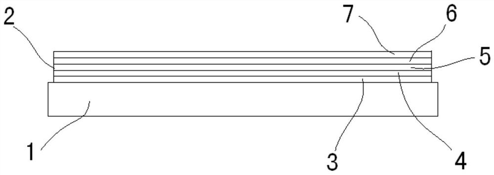
[0043] Embodiment one, such as figure 1 As shown, the anti-reflection film 2 disposed on the substrate layer 1 includes a five-layer structure, that is, a first low-reflection layer 3, a second low-reflection layer 4, and a third low-reflection layer 5 belonging to a multilayer film, and a protective film. The first protective film 6 and the second protective film 7 of the film.

Embodiment 2

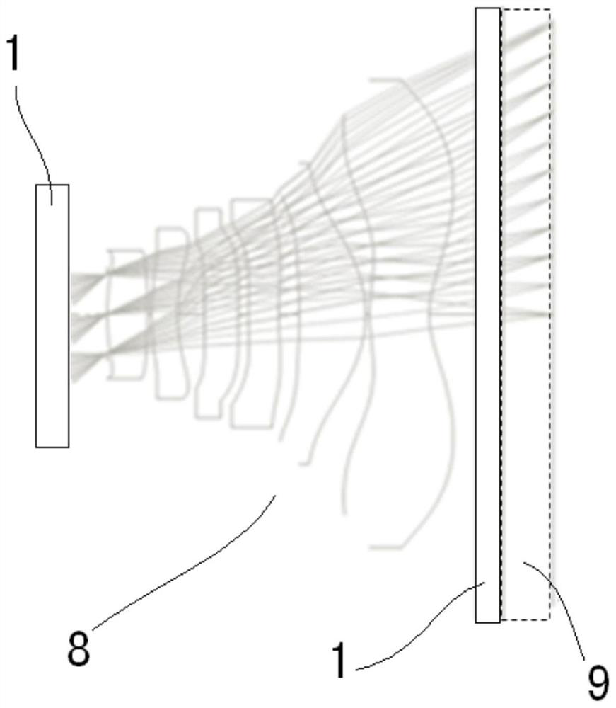
[0044] Embodiment two, such as figure 1 , figure 2 Shown, is the optical component 8 structure that adopts substrate layer 1 and anti-reflection film 2 of the present invention, one end of optical component 8 contacts with air layer 9, and optical component 8 two ends are respectively provided with substrate layer 1, and optical element 8 is contained in On the basis of lenses, optical filters, etc., at least one of the light entrance and exit surfaces of the substrate layer 1 includes an antireflection film 2, and the antireflection film 2 is formed from the substrate layer 1 side or the substrate layer 1 side to the On the air layer 9 side, the first low-reflection layer 3, the second low-reflection layer 4, the third low-reflection layer 5, the first layer of protective film 6, and the second layer of protective film 7 are stacked on the substrate layer 1 to form .

[0045] The specific implementation process is that in this embodiment, the first low-reflection layer 3 o...


PUM

PropertyMeasurementUnit
thicknessaaaaaaaaaa
wavelengthaaaaaaaaaa

Abstract

The invention discloses an anti-reflection film. The anti-reflection film is arranged on the surface of a substrate layer. The antireflection film includes a multilayer film arranged on the surface of the substrate layer and a protective film arranged outside the multilayer film. The multi-layer film is formed by stacking two or three low-reflection layers, and the outer side of the multi-layer film of the anti-reflection film is provided with two layers of protective films in sequence; and an optical component comprising the anti-reflection film, the The anti-reflection film is provided on both sides or one side of the optical component filter. The present invention can obtain an anti-reflection film with high performance and anti-reflection performance for broadband wavelengths from 400nm to 800nm, and when the anti-reflection film is used in an optical system, ghosting or flare can be reduced.

Description

technical field [0001] The invention relates to the technical field of optical equipment, in particular to an anti-reflection film and an optical component comprising the anti-reflection film. Background technique [0002] Most of the optical elements included in the optical system, such as lenses and optical filters, are made of transparent members (substrates) such as optical glass or optical plastics. When the refractive index of such a substrate increases, the light incident surface and the light exit surface ( The reflectance of the light entrance and exit surface) will become higher. If an optical element with a high reflectance of the light entrance and exit surface is used, the effective amount of light reaching the image surface will decrease, and unnecessary reflection from the light entrance and exit surface of the optical element will be reduced. Reflection and incident on the image plane will cause ghosting and flare, which will reduce the optical performance of...

Claims


Application Information

Patent Timeline
Patent Type & Authority Patents(China)
IPC IPC(8): G02B1/115
CPCG02B1/115G02B5/0294G02B1/11G02B1/14Y10T428/2495G02B1/111
Inventor 葛文志木村隆志
Owner HANGZHOU MDK OPTO ELECTRONICS CO LTD
Why Eureka
Try Eureka