Supercharge Your Innovation With Domain-Expert AI Agents!

Integrated machine structure of vacuum pump and recovery machine

A vacuum pump and recovery machine technology, applied in the direction of machines/engines, pumps, piston pumps, etc., can solve the problems of inconvenient portability and use, separate configuration, high procurement costs, etc., to reduce processing accuracy and assembly difficulty, easy to use, and universal Good results

Active Publication Date: 2020-08-18
ZHEJIANG VALUE MECHANICAL & ELECTRICAL PROD CO LTD
View PDF7 Cites 0 Cited by
  • Summary
  • Abstract
  • Description
  • Claims
  • Application Information

AI Technical Summary

Problems solved by technology

[0003] The present invention mainly provides an integrated machine structure of a vacuum pump and a recovery machine that is easy to use, high in reliability, low in cost, energy-saving and environment-friendly, and solves the need to separately configure the recovery machine and the vacuum pump in the prior art for refrigeration maintenance, not only Inconvenient to carry and use, and technical problems such as high procurement costs

Method used


Image

  • Integrated machine structure of vacuum pump and recovery machine
  • Integrated machine structure of vacuum pump and recovery machine
  • Integrated machine structure of vacuum pump and recovery machine

Examples


Embodiment

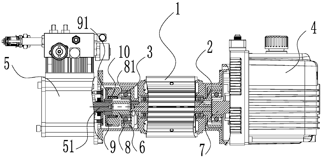
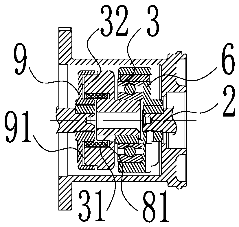
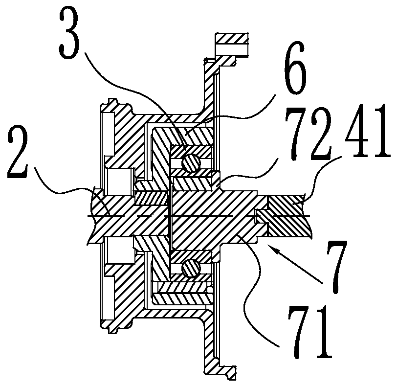
[0019] Such as figure 1 As shown, including the motor 1, the motor 1 can be a brushless motor or an AC motor, the two ends of the output shaft 2 of the motor 1 respectively extend to the outside of the motor 1, and the two left and right ends of the output shaft 2 are respectively keyed to the bearing seat 6 One-way clutch bearings 3 are installed on the corresponding output shafts 2 outside the bearing housing 6, and the one-way clutch bearings 3 are embedded and fixed in the outer ring groove of the bearing housing 6, and the corresponding one-way clutch bearings 3 at the right end The vacuum pump end mandrel 7 is interfitted and inserted into the middle hole, and the outer end of the vacuum pump end mandrel 7 is connected to the rotor shaft 41 of the vacuum pump 4 with a coaxial key, and the corresponding one-way clutch bearing 3 on the left side is interfitted and inserted in the middle hole. Compressor end mandrel 8, compressor end mandrel 8 is coaxially connected to the ...


PUM


Abstract

The invention relates to the field of refrigeration maintenance, and provides a vacuum pump and recycling machine integrated machine structure which is convenient to use, high in reliability, low in cost, and capable of saving energy and protecting the environment. The technical problems that in the prior art, during refrigeration maintenance, a recycling machine and a vacuum pump need to be separately configured, carrying and using are inconvenient, and the purchasing cost is high are solved. The vacuum pump and recycling machine integrated machine structure comprises a motor, the two ends ofan output shaft of the motor extend out of the motor, the two ends of the output shaft are connected with a rotor shaft of the vacuum pump and a compressor crankshaft on the recycling machine throughunidirectional clutch bearings correspondingly, when the rotation direction of the output shaft is changed, one end of the output drives the corresponding vacuum pump or a corresponding compressor torotate synchronously, and the other end of the output shaft is separated from the corresponding vacuum pump or the corresponding compressor.

Description

technical field [0001] The invention relates to the field of refrigeration maintenance, in particular to an integrated machine structure of a vacuum pump and a recovery machine which is convenient to use, high in reliability, energy-saving and environment-friendly. Background technique [0002] In the existing refrigeration maintenance field, the general refrigerant recovery machine and the vacuum pump are configured separately. During the refrigeration maintenance process, the refrigerant in the refrigeration system needs to be pumped out with a recovery machine, after the maintenance is completed, the system is evacuated with a vacuum pump, and finally the refrigerant is refilled into the system. It is necessary to carry a recovery machine and a vacuum pump for maintenance, which is not only inconvenient to carry and use, but also requires high procurement costs for separately configuring the recovery machine and vacuum pump, resulting in increased user costs. Contents o...

Claims


Application Information

Patent Timeline
Patent Type & Authority Patents(China)
IPC IPC(8): F04B35/04F04B41/06F04B39/00F25B45/00
CPCF04B35/04F04B39/0094F04B41/06F25B45/00F25B2345/001F25B2345/002
Inventor 蒋友荣
Owner ZHEJIANG VALUE MECHANICAL & ELECTRICAL PROD CO LTD
Features
  • R&D
  • Intellectual Property
  • Life Sciences
  • Materials
  • Tech Scout
  • Unparalleled Data Quality
  • Higher Quality Content
  • 60% Fewer Hallucinations
Learn More