Charging control circuit, terminal equipment and control method

A technology of charging control and control method, applied in the field of communication, can solve the problems of low wireless charging efficiency and the like, and achieve the effect of improving efficiency

Active Publication Date: 2019-04-23
VIVO MOBILE COMM CO LTD
View PDF4 Cites 5 Cited by
  • Summary
  • Abstract
  • Description
  • Claims
  • Application Information

AI Technical Summary

Problems solved by technology

[0004] Embodiments of the present invention provide a charging control circuit, a terminal device a

Method used


Image

  • Charging control circuit, terminal equipment and control method
  • Charging control circuit, terminal equipment and control method
  • Charging control circuit, terminal equipment and control method

Examples


Embodiment Construction

[0022] The following will clearly and completely describe the technical solutions in the embodiments of the present invention with reference to the accompanying drawings in the embodiments of the present invention. Obviously, the described embodiments are some of the embodiments of the present invention, but not all of them. Based on the embodiments of the present invention, all other embodiments obtained by persons of ordinary skill in the art without creative efforts fall within the protection scope of the present invention.

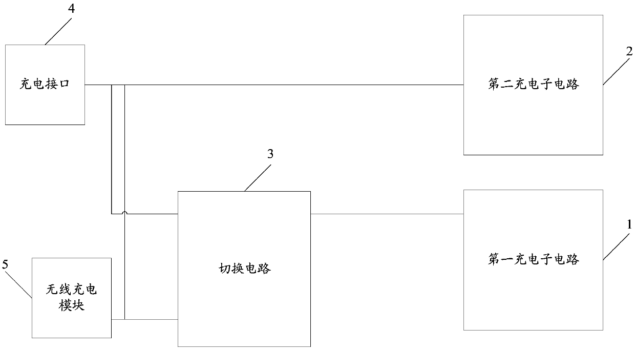
[0023] see figure 1 , figure 1 is a structural diagram of the charging control circuit provided by the embodiment of the present invention, such as figure 1 As shown, it includes a first charging sub-circuit 1 and a second charging sub-circuit 2, the charging efficiency of the first charging sub-circuit 1 is greater than that of the second charging sub-circuit 2, and the charging control circuit also includes a switching Circuit 3; the first contact ...


PUM


Abstract

The invention provides a charging control circuit, terminal equipment and a control method. The charging control circuit comprises a first charging sub-circuit and a second charging sub-circuit, wherein the charging efficiency of the first charging sub-circuit is greater than that of the second charging sub-circuit; the charging control circuit further comprises a switching circuit; a first contact of the switching circuit is connected with a charging interface; a second contact of the switching circuit is connected with an output end of a wireless charging module; a third contact of the switching circuit is connected with an input end of the first charging sub-circuit; under a wireless charging condition, the first contact and the third contact are disconnected, and the second contact andthe third contact are conducted. Therefore, the first charging sub-circuit with relatively great charging efficiency can be used for charging under the wireless charging condition and the wireless charging efficiency of the terminal equipment is improved.

Description

technical field [0001] The invention relates to the field of communication technology, in particular to a charging control circuit and a control method. Background technique [0002] With the rapid development of terminal technology, terminal equipment has become an indispensable tool in people's life, and brings great convenience to all aspects of users' life. And with the development of the wireless charging technology, the application of the wireless charging function in the terminal equipment is becoming more and more popular. The principle of wireless charging technology is to transmit energy between the charger and the terminal device with a magnetic field, and there is no need for wires to connect the two. It is very convenient to use and is very popular among users. [0003] However, in the prior art, the efficiency of using wireless charging for terminal equipment is relatively low. Contents of the invention [0004] Embodiments of the present invention provide ...

Claims


Application Information

Patent Timeline
IPC IPC(8): H02J7/00
CPCH02J7/0077H02J2207/40H02J7/007H02J7/0068H02J50/12H02J7/007182H02J7/007194H02J7/00712H02J50/00G01R19/16542Y02B40/00H02J50/10H02J7/0071
Inventor 廖兴保
Owner VIVO MOBILE COMM CO LTD
Why Eureka
Try Eureka