Wireless charging receiving apparatus, wireless charging system and charging control method thereof

A technology for wireless charging and receiving devices, applied in circuit devices, battery circuit devices, current collectors, etc., can solve the problems of reduced wireless charging efficiency and large resonance frequency error, and achieve the effect of improving wireless charging efficiency

Inactive Publication Date: 2017-01-04
HISENSE VISUAL TECH CO LTD
View PDF4 Cites 4 Cited by
  • Summary
  • Abstract
  • Description
  • Claims
  • Application Information

AI Technical Summary

Problems solved by technology

[0005] Based on this, an object of the present disclosure is to provide a wireless charging receiving device, which is used to solve the problem in the prior art that the efficiency of wireless charging is reduced due to the large error between the resonant frequency of the receiving end and the resonant frequency of the transmitting end.
[0006] In addition, another object of the present disclosure is to provide a wireless charging system and its charging control method, which is used to solve the problem in the prior art that the efficiency of wireless charging is reduced due to the large error between the resonant frequency of the receiving end and the resonant frequency of the transmitting end.

Method used


Image

  • Wireless charging receiving apparatus, wireless charging system and charging control method thereof
  • Wireless charging receiving apparatus, wireless charging system and charging control method thereof
  • Wireless charging receiving apparatus, wireless charging system and charging control method thereof

Examples


Embodiment Construction

[0022] Reference will now be made in detail to exemplary embodiments, examples of which are illustrated in the accompanying drawings. When the following description refers to the accompanying drawings, the same numerals in different drawings refer to the same or similar elements unless otherwise indicated. The implementations described in the following exemplary examples do not represent all implementations consistent with the present disclosure. Rather, they are merely examples of apparatuses and methods consistent with aspects of the present disclosure as recited in the appended claims.

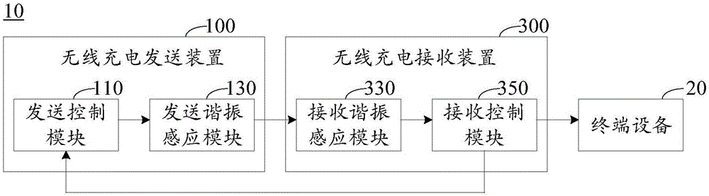
[0023] figure 1 is a block diagram of a wireless charging system involved in the present disclosure, such as figure 1 As shown, the wireless charging system 10 includes a wireless charging sending device 100 and a wireless charging receiving device 300 .

[0024] Wherein, the wireless charging sending device 100 includes but not limited to: a sending control module 110 and a sending reso...


PUM


Abstract

The invention relates to a wireless charging receiving apparatus, a wireless charging system and a charging control method thereof. The wireless charging receiving apparatus includes: a frequency modulation control module, a receiving resonance sensing module and a receiving control module. The frequency modulation control module is intended for pooling a plurality of preset states, detecting the peak value of a first output end of the receiving resonance sensing apparatus, and obtaining the best state from the polled preset states; the receiving resonance sensing module is intended for, on the basis of the best state, setting capacitance value in LC resonance so as to regulate the resonance frequency of the LC resonance, outputting the largest charging current by regulating and controlling a second output end, the LC resonance being formed in the receiving resonance sensing module; and the receiving control module is intended for conducting DC conversion on the largest charging current and then outputting the largest charging current that undergoes DC conversion to a to-be-charged load. According to the invention, the wireless charging receiving apparatus enables the resonance frequency of a receiving end to approach the resonance frequency of a transmitting end, thus increasing the efficiency of wireless charging.

Description

technical field [0001] The present disclosure relates to the technical field of wireless charging, and in particular to a wireless charging receiving device, a wireless charging system and a charging control method thereof. Background technique [0002] At present, the wireless charging technology has been widely used in the charging process of the terminal equipment, for example, the WPC (Wireless Power Consortium, wireless power consortium) technical standard. [0003] The WPC technical standard uses the receiving end to magnetically induce the current generated by the sending end, controls the wireless charging system to output charging current to the load to be charged, and at the same time the receiving end feeds back the output to the sending end, and then controls the end of the wireless charging process through the sending end. [0004] Due to the errors in the production parameters and material parameters of the terminal equipment, in the process of wireless chargin...

Claims


Application Information

Patent Timeline
Patent Type & Authority Applications(China)
IPC IPC(8): H02J50/12H02J7/00
CPCH02J7/025H02J7/0036
Inventor 沈润渊贾佳
Owner HISENSE VISUAL TECH CO LTD
Why Eureka
Try Eureka