Signal acquisition device, screen signal acquisition device and method

A signal acquisition and screen technology, applied in the field of signal processing, can solve the problems of image recognition quality degradation and grid-to-stripe, and achieve the effect of improving image recognition quality and eliminating grid-to-stripes

Active Publication Date: 2019-05-10
CHIPONE TECH BEIJINGCO LTD
View PDF5 Cites 2 Cited by
  • Summary
  • Abstract
  • Description
  • Claims
  • Application Information

AI Technical Summary

Problems solved by technology

There will be noise or fluctuation in the output of the gate driver chip / array substrate row driver (GOA, Gate Driver on Array), and other factors such as crosstalk between the panel and the adjacent layer of the photodiode sensor array will also be in the form of noise Superimposed on the signal collected by the readout chip, resulting in gate stripes, resulting in a decrease in image recognition quality

Method used


Image

  • Signal acquisition device, screen signal acquisition device and method
  • Signal acquisition device, screen signal acquisition device and method
  • Signal acquisition device, screen signal acquisition device and method

Examples


Embodiment 1

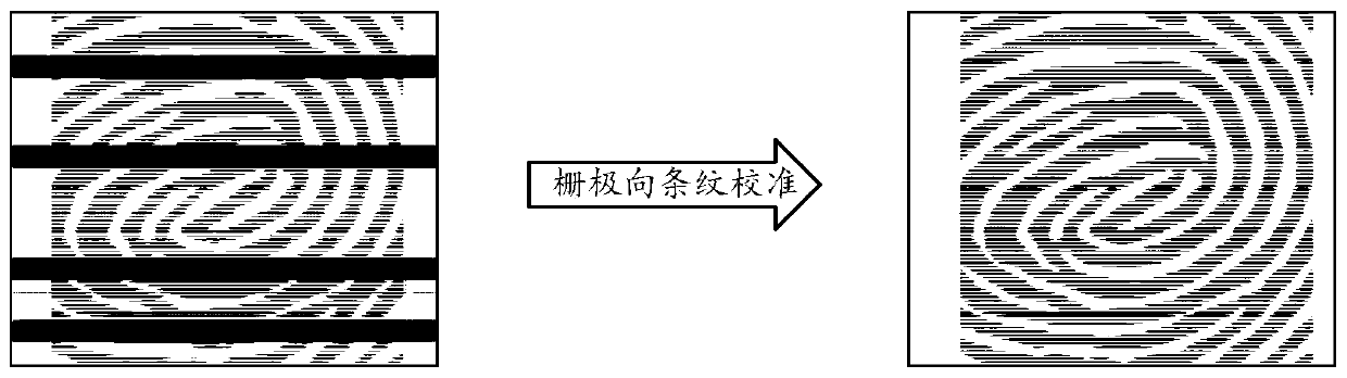
[0035] An embodiment of the present invention provides a signal acquisition device, which includes a first sensing array and at least one second sensing array; the number of channels in the first channel direction of the second sensing array is consistent with that of the first sensing array , and the first channel of the second sensing array is correspondingly connected to the first channel of the first sensing array; when any target channel in the first channel direction of the first sensing array is opened, the second sensing array collects Volatility signal of the target channel.

[0036] see image 3 , is a structural schematic diagram of the signal acquisition device, in image 3 In the illustrated embodiment, the signal acquisition device 10 includes a photodiode sensor array 11 and at least one dummy sensor array 12 (Dummy SensorArray). Wherein, the dummy sensor array 12 and the photodiode sensor array 11 have the same number of gate rows, and each gate line is corresp...

Embodiment 2

[0046] see Figure 4 , which is a schematic structural diagram of a screen signal acquisition device provided by an embodiment of the present invention, consisting of Figure 4 It can be seen that the device includes a readout chip 20 , a gate drive circuit 30 , and the signal acquisition device 10 provided in the first embodiment and one of its possible implementations above.

[0047] In the screen signal acquisition device, the readout chip 20 includes a conventional analog front end matching with the photodiode sensor array 11 and a dummy analog front end (Dummy Analog Front End) matching with the dummy sensor array. Wherein, the source line of the photodiode sensor array 11 is connected to the signal input end of the conventional analog front end, and the source line of the dummy sensor array is connected to the signal input end of the dummy analog front end.

[0048] Here, the conventional analog front end is used to receive electrical signals output from each source lin...

Embodiment 3

[0056] An embodiment of the present invention also provides a screen signal collection method, which is applied to the screen signal collection device provided in the second embodiment and one of its possible implementations, see Figure 6 , which is a flow diagram of the method, by Figure 6 Visible, this method comprises the following steps:

[0057] Step S602: The readout chip receives the position information of the trigger area of ​​the screen.

[0058] Here, the screen can be a screen of various terminals such as a mobile phone, a tablet, and a notebook computer, and the screen includes the screen signal acquisition device provided in the second embodiment above. Taking the application in a mobile phone as an example, when a finger touches the screen, it is received The pressure area is triggered, and the location information of the trigger area is obtained. In one embodiment, the application processor may first obtain the location information of the trigger area from t...


PUM


Abstract

The invention provides a signal acquisition device and a screen signal acquisition device and method, and relates to the technical field of signal processing, the signal acquisition device comprises afirst sensing array and at least one second sensing array; the number of channels in the first channel direction of the second sensing array is consistent with that of channels in the first channel direction of the first sensing array, and the first channels of the second sensing array are correspondingly connected with the first channels of the first sensing array; when any target channel in thefirst channel direction of the first sensing array is opened, the second sensing array collects the fluctuation signal of the target channel. According to the signal acquisition device, the screen signal acquisition device and the screen signal acquisition method provided by the embodiment of the invention, the grid fluctuation signal of each grid line in the photodiode sensor array can be acquired in real time so as to eliminate grid directional stripes, and the image recognition quality is effectively improved.

Description

technical field [0001] The present invention relates to the technical field of signal processing, in particular to a signal acquisition device, a signal acquisition device and a method. Background technique [0002] Optical fingerprint recognition usually uses the screen of the terminal device as the light-emitting body, irradiates the fingerprint through the optical path, and the returned light passes through the screen and returns to the image sensor under the screen. The terminal device analyzes and compares the returned image with the database to finally identify the fingerprint. Optical fingerprint recognition uses the principle of refraction and reflection of light. The light that hits the ridges (protrusions between the lines) on the surface of the finger will be totally reflected, and the reflected light will be projected onto the image sensor to form a black image. The light on the valley line of the finger (the concave part between the lines) is absorbed by the fin...

Claims


Application Information

Patent Timeline
Patent Type & Authority Applications(China)
IPC IPC(8): G06K9/00
Inventor 李伟江
Owner CHIPONE TECH BEIJINGCO LTD
Why Eureka
Try Eureka