Barcode identifying and reading device

A barcode and equipment technology, applied in the field of barcode recognition, can solve the problems that barcode reading equipment cannot read and decode normally, cannot realize long-distance scanning and decoding, barcode image interference, etc., so as to improve the clarity, improve the decoding success rate, The effect of fast decoding

Pending Publication Date: 2019-05-24
福州符号信息科技有限公司
View PDF4 Cites 4 Cited by
  • Summary
  • Abstract
  • Description
  • Claims
  • Application Information

AI Technical Summary

Problems solved by technology

Existing passive scanning barcode reading equipment can only scan codes at short distances. When scanning codes at long distances, the light incident on the lens contains a lot of external environment stray light. For example, mobile terminals used to display identification codes Specular reflection light on the surface, multi-angle astigmatism in natural light, and other high-brightness external lighting sources, etc., these stray lights have caused serious interference to the image sensor to capture the barcode image, making the image noise in the captured image too high, barcode reading The device cannot read and decode normally, such as figure 1 As shown, the barcode image captured when the existing single-lens barcode reading equipment scans the barcode at 60cm, the barcode in the picture is interfered by strong light, and cannot be read and decoded
Existing reading devices used for passive code scanning not only cannot realize long-distance scanning and decoding, but also cannot realize both short-distance and long-distance scanning and decoding

Method used


Image

  • Barcode identifying and reading device
  • Barcode identifying and reading device
  • Barcode identifying and reading device

Examples


Embodiment Construction

[0044] The present invention will be described in detail below in conjunction with the accompanying drawings and specific embodiments.

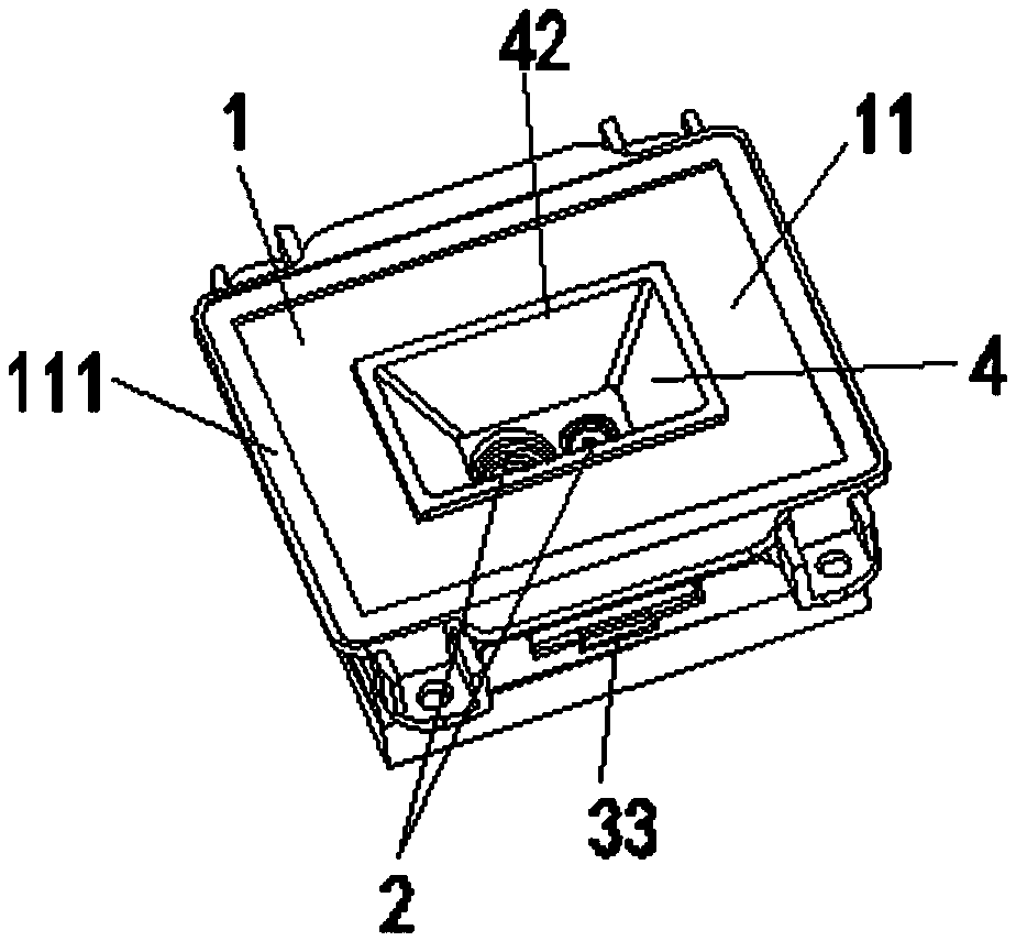
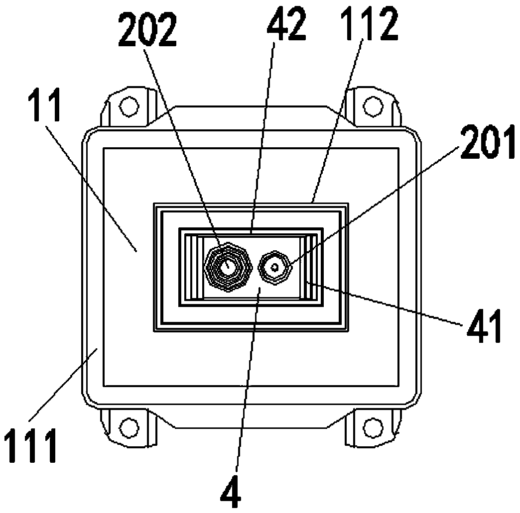
[0045] see Figure 2 to Figure 4 , a barcode reading device, comprising a housing 1, a slot-shaped viewing window 4, and a camera unit and a circuit board 3 arranged in the housing 1, the front side 11 of the housing 1 is provided with a hole 12, the slot Type finder window 4 is sleeved in this hole 12, and the depth value D of described groove finder window 4 1≥10mm, the camera unit includes at least two camera modules 2, each camera module 2 includes a lens 21 and an image sensor 23, each lens 21 is fixed on the bottom of the viewfinder window 4, and each lens 21 through the window 42 of the slot-type viewfinder 4 (the window 42 is the outermost opening of the slot-type viewfinder 4), and each image sensor 23 receives the light signal incident by the lens 21 and converts the light signal After being an electrical signal, it is sent to the...


PUM


Abstract

The invention relates to bar code identifying and reading equipment. The camera comprises a shell, and a camera unit and a circuit board which are arranged in the shell, The device further comprises agroove-shaped view-finding window. A hole is formed in the front face of the shell. The groove type view finding window is sleeved in the hole; the depth value D1 of the groove type view finding window is greater than or equal to 10 mm; the camera shooting unit comprises at least two camera shooting modules; each camera module comprises a lens and an image sensor; wherein each lens is fixed at the bottom of the framing window, each lens collects a bar code image through a window of the groove-shaped framing window, and each image sensor receives an optical signal incident from the lens, converts the optical signal into an electric signal and sends the electric signal to a processor on the circuit board for decoding to obtain bar code information. The bar code reading device can be provided with a plurality of camera modules, code scanning requirements of multiple modes in different brightness environments can be met at the same time, and meanwhile, the view finding window is arrangedto limit incident angles of stray light and improve definition of bar code images.

Description

technical field [0001] The invention relates to a barcode reading device, which belongs to the field of barcode identification. Background technique [0002] The patent for invention with the publication number CN107111737A "Double-camera scanning gun and its scanning method" discloses that a near-focus camera and a far-focus camera are installed in the scanning gun to expand the depth of field of the scanning gun, but it must be carried out by manually holding the scanning gun. Scanning the code, manually adjusting the angle of the scanning gun during the scanning process so that the camera can capture a clear barcode image, which uses an active code scanning method, which cannot meet the needs of unmanned code scanning. Most of the existing barcode reading devices for passive scanning (the barcode recognition device is fixed) are mostly single-camera, and the user holds the mobile terminal, and the identification code on the mobile terminal is close or close to the barcode...

Claims


Application Information

Patent Timeline
Patent Type & Authority Applications(China)
IPC IPC(8): G06K7/10
Inventor 吴文彬
Owner 福州符号信息科技有限公司
Why Eureka
Try Eureka