Stacked packaging case lifting device

A technology for packing boxes and suitcases, which is applied in the direction of lifting devices, lifting frames, etc., which can solve the problems of inconvenient operation, high overall cost, and shortened service life of guide posts, and achieve the effects of prolonging service life, low overall cost, and convenient operation

Inactive Publication Date: 2019-05-28
济南群星科技有限公司
View PDF0 Cites 0 Cited by
  • Summary
  • Abstract
  • Description
  • Claims
  • Application Information

AI Technical Summary

Problems solved by technology

[0002] After the printed packing boxes are stacked, they need to be transferred and transported to the transport vehicle. The traditional lifting devices are all rigid contacts, without shock buffer devices, which may easily cause one end of the suitcase beam to appear due to the sudden lifting action of the stacked packing boxes. The phenomenon of high end and low end, accompanied by the phenomenon of "crawling", will lead to the deformation of the guide column in severe cases, which will aggravate the occurrence of asynchronous phenomenon, make the guide column wear quickly, shorten the service life of the guide column, and require high maintenance; Moreover, due to the difference in the flow rate between the oil cylinder and the oil cylinder and the manufacturing accuracy of the guide column and movable support, the problem of unbalanced crossbeam of the suitcase will also occur; the traditional lifting device also has the problems of complex structure, inconvenient operation, and high overall cost.

Method used


Image

  • Stacked packaging case lifting device
  • Stacked packaging case lifting device
  • Stacked packaging case lifting device

Examples


Embodiment Construction

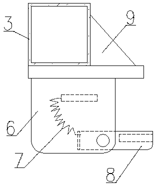
[0020] Accompanying drawing is a kind of specific embodiment of the present invention.

[0021] The lifting device for stacked packing boxes of the present invention includes a carrying case beam 3 and a bracket, and is characterized in that: rollers 2 are arranged on the tops of both ends of the carrying case cross beam 3, and an oil cylinder upper seat 4 is respectively fixed on the lower sides of the two ends of the carrying case cross beam 3. The inboard of the upper seat 4 of the oil cylinder is also respectively provided with a suitcase hanging plate 5; The suitcase hanging plate 5 is composed of a suitcase brace 6, a suitcase flap 8 and a tension spring 7, the suitcase brace 6 is movably connected with the suitcase flap 8, and the suitcase brace 6 and the suitcase flap 8 are provided with a spring Draw the hole, and the tension spring 7 is connected with the tension of the two draw holes. A reinforcing rib 9 is also fixed between the suitcase hanging board 5 and the su...


PUM


Abstract

The invention belongs to the field of packaging processing, and particularly relates to a stacked packaging case lifting device. The lifting device comprises a case lifting cross beam and a support, the device is characterized in that rotating wheels are arranged at the tops of the two ends of the case lifting cross beam, the lower sides of the two ends of the case lifting cross beam are respectively and fixedly provided with an oil cylinder upper seat, the inner sides close to the oil cylinder upper seat is further provided with a case lifting hanging plate respectively, the support is of anN-shaped structure, sliding rails are arranged on the inner sides of the left side support and the right side support, and the rotating wheels of the case lifting cross beam freely slide in the sliding rails. The device has the beneficial effects that the case lifting cross beam is movably connected with the rotating wheels of the support, so that the case lifting cross beam and the rotating wheels are not easy to damage, and the service life is prolonged; the two sides of the case lifting cross beam are respectively provided with the oil cylinder upper seat for installing an oil cylinder, thetwo ends of the lifting process are simultaneously stressed, and the lifting process is more stable and safer compared with a traditional single oil cylinder; the whole device is simple in structure,convenient to operate, low in overall cost and easy to popularize compared with a traditional device.

Description

technical field [0001] The invention belongs to the field of packaging processing, and in particular relates to a lifting device for stacked packing boxes. Background technique [0002] After the printed packing boxes are stacked, they need to be transferred and transported to the transport vehicle. The traditional lifting devices are all rigid contacts, without shock buffer devices, which may easily cause one end of the suitcase beam to appear due to the sudden lifting action of the stacked packing boxes. The phenomenon of high end and low end, accompanied by the phenomenon of "crawling", will lead to the deformation of the guide column in severe cases, which will aggravate the occurrence of asynchronous phenomenon, make the guide column wear quickly, shorten the service life of the guide column, and require high maintenance; Moreover, due to the difference in the flow rate between the oil cylinders and the manufacturing accuracy of the guide pillars and movable supports, t...

Claims


Application Information

Patent Timeline
Patent Type & Authority Applications(China)
IPC IPC(8): B66F7/20B66F7/28
Inventor 董金朝
Owner 济南群星科技有限公司
Why Eureka
Try Eureka