Display panel and display device

A display panel and display area technology, which is applied in the direction of identification devices, instruments, TVs, etc., can solve the problems of affecting the look and feel of the display panel, different reflectivity and brightness, and weakened light intensity, so as to improve display uniformity and reduce light intensity. Effect

Inactive Publication Date: 2019-05-28
SHANGHAI TIANMA MICRO ELECTRONICS CO LTD
View PDF9 Cites 41 Cited by
  • Summary
  • Abstract
  • Description
  • Claims
  • Application Information

AI Technical Summary

Problems solved by technology

However, the full screen includes the reserved area for optical and electronic components and the conventional display area. The reserved area for optical and electronic components is used for display at the same time. Since the polarizer will reduce the light intensity, it is necessary to obtain sufficient light for the normal operation of the optical and electronic components. The reserved area for optical and electronic components is not suitable for setting polarizers, so in a full screen, polarizers are only installed in the regular display area, resulting in differences in reflectivity and brightness between the reserved area for optical and electronic components and the regular display area, affecting the look and feel of the display panel

Method used


Image

  • Display panel and display device
  • Display panel and display device
  • Display panel and display device

Examples


Embodiment Construction

[0022] In order to further explain the technical means and effects of the present invention to achieve the intended purpose of the invention, the following describes the specific implementation, structure, and features of a display panel and display device according to the present invention with reference to the accompanying drawings and preferred embodiments. And its effects are described in detail later.

[0023] The embodiment of the present invention provides a display panel including a display area;

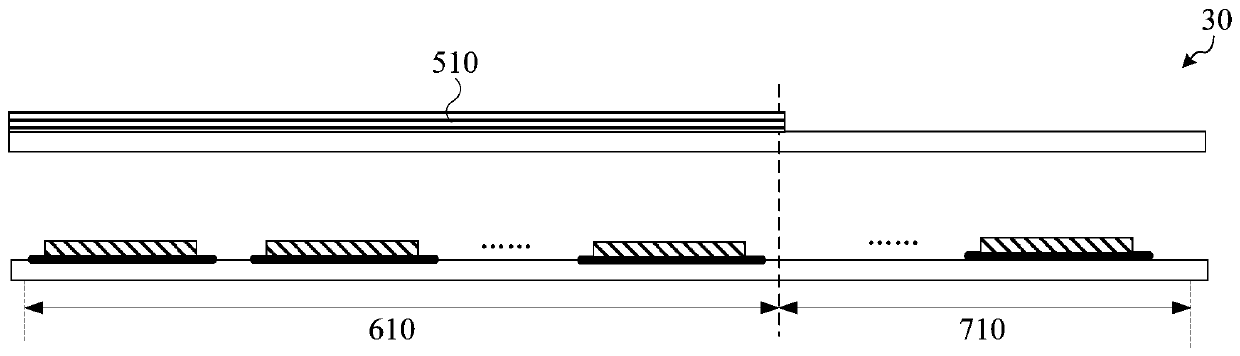
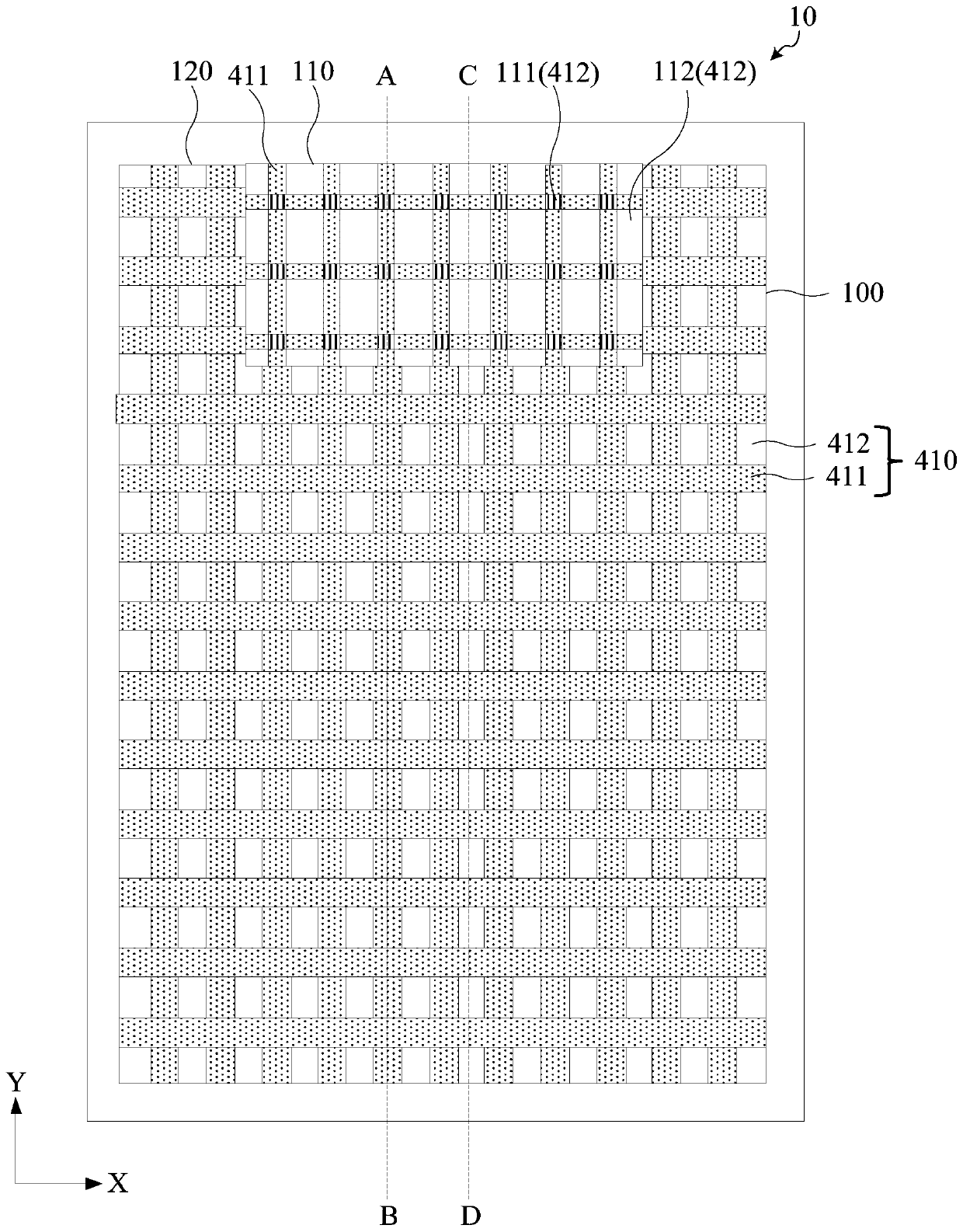
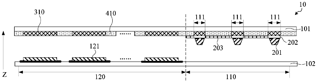
[0024] The display area includes a first display area and a second display area, the first display area is multiplexed into a reserved area for optical electronic elements, and the first display area includes a light-emitting area and a light-transmitting area;

[0025] In the first display area, the display panel includes a plurality of micro LEDs, and the micro LEDs are located in the light-emitting area;

[0026] In the second display area, the display panel includes a plurality ...


PUM


Abstract

The invention discloses a display panel and a display device. The display panel comprises a display area; the display area comprises a first display area and a second display area; the first display area comprises a light-emitting area and a light-transmitting area and is multiplexed into an optical electronic component reserved area; in the first display area, the display panel comprises a plurality of micro LEDs which are positioned in the light-emitting area; in the second display area, the display panel comprises a plurality of organic light-emitting units; the display panel further comprises a colorful light filter layer, the colorful light filter layer comprises a plurality of color resistance units, and the color resistance units are superposed with the micro LEDs in the first display area and are superposed with the organic light-emitting units in the second display area; light emitted by the micro LEDs and light emitted by the organic light-emitting units are used for displaying images after being emerged by the color resistance units. According to the technical scheme provided by the embodiment of the invention, the problem that the reflectivity and the brightness of thefirst display area are different from those of the second display area as a polaroid is only arranged in the second display area is solved, and the influence of reflected light on the display effect of the display panel is reduced.

Description

Technical field [0001] The embodiments of the present invention relate to the field of display technology, and in particular to a display panel and a display device. Background technique [0002] When the display panel has a mirror effect, the user can see his own image on the display panel, which interferes with obtaining the display image of the display panel, and affects the user experience. [0003] In the prior art, the above-mentioned problem is solved by disposing a polarizer on the light emitting surface side of the display panel. However, the full screen includes a reserved area for optical and electronic components and a conventional display area. The reserved area for optical and electronic components is used for display at the same time. As the polarizer will reduce the light intensity, it is necessary to obtain sufficient light to work properly where the optical and electronic components are located. The reserved area for optical and electronic components is not suita...

Claims


Application Information

Patent Timeline
Patent Type & Authority Applications(China)
IPC IPC(8): G09F9/33H01L27/32G09F9/30H04N5/225
Inventor 符鞠建
Owner SHANGHAI TIANMA MICRO ELECTRONICS CO LTD
Why Eureka
Try Eureka