An infusion device driven by a piezoelectric stack

The technology of an infusion device and a piezoelectric stack, which is applied in the field of medical devices, can solve the problems of unfavorable drug absorption and utilization, increase the burden on the heart, and shorten the infusion time, so as to avoid uneven blood drug concentration, facilitate movement and portability, and improve drug delivery. The effect of curative effect

Active Publication Date: 2021-03-12
ZHEJIANG NORMAL UNIVERSITY
View PDF17 Cites 0 Cited by
  • Summary
  • Abstract
  • Description
  • Claims
  • Application Information

AI Technical Summary

Problems solved by technology

This infusion mode will bring many problems in actual use: the flow rate is adjusted manually, and the flow control accuracy is not enough; the infusion bottle needs to be held high by others when the patient walks or goes to the toilet, which is inconvenient to move and the height of the infusion bottle is not high enough. Make the blood flow back; patients or nurses need to be guarded for a long time, if the infusion is not found in time, it may cause accidents; the liquid medicine is in contact with the air, and the ambient air may be polluted when the air is unclean
In addition to the above direct problems, sometimes the infusion time is shortened by reducing the amount of solution, speeding up the infusion speed, etc., which not only increases the burden on the heart, but also affects the therapeutic effect: intramuscular injection and subcutaneous injection in a relatively short period of time. The biggest disadvantage of injecting into muscle or subcutaneous is that the blood drug concentration varies greatly within an injection cycle, which is not conducive to the effective absorption and utilization of drugs, because most drugs have a better concentration range in the human body, and when the drug concentration is too high Has toxic side effects, if it is too low, it will have no therapeutic effect

Method used


Image

  • An infusion device driven by a piezoelectric stack
  • An infusion device driven by a piezoelectric stack
  • An infusion device driven by a piezoelectric stack

Examples


Embodiment Construction

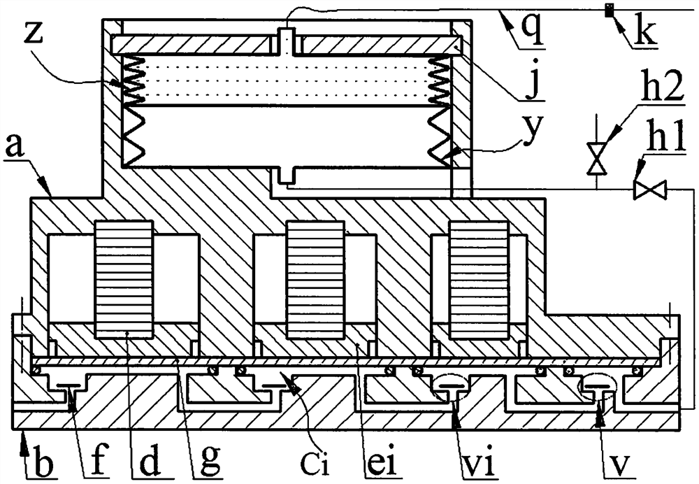
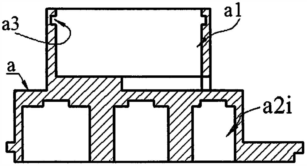
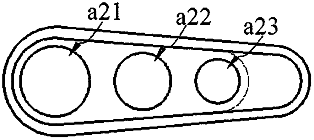
[0013] The base b is provided with an inlet hole b1, at least two sink chambers b2i with different diameters, an outlet chamber b3 and an outlet hole b6, the diameters of the sink chamber b2i decrease successively from left to right, and the bottom wall of the sink chamber b2i is provided with The inlet b4 and the air outlet b5, the inlet b4 of the leftmost sink chamber b2i is connected with the inlet b1, the air outlet b5 of the rightmost sink b2i is connected with the outlet b6 through the outlet b3, and the other two adjacent sink chambers The inlet b4 and the air outlet b5 of b2i are connected to each other; the inlet b4 and the outlet b3 and the valve plate f installed in them constitute the inlet valve vi and the outlet valve v respectively, and the valve f is a cantilever beam valve or a disc valve; the main body The bottom of a is provided with guide holes a2i equal in number and diameter to the sink cavity b2i; the main body a is installed on the base b through screws ...


PUM


Abstract

The invention relates to a transfusion device driven by a piezoelectric stack, which belongs to the field of medical equipment. The base is provided with an entrance and exit hole, an exit cavity and at least two sinking cavities with different diameters. The diameters of the sinking cavity decrease successively from left to right. The installed valves constitute the inlet and outlet valves; the bottom of the main body is provided with guide holes equal in number and diameter to the sink cavity, the main body is installed on the base and the diaphragm is crimped on the base, and the guide holes and the sink cavity are symmetrically arranged on both sides of the diaphragm ; The piezoelectric stack in the guide hole crimps the piston on the diaphragm; the diaphragm crimps the sealing ring in the sink cavity to form a series of compression chambers; The end of the side wall is equipped with a baffle; the liquid outlet pipe of the medicine bag is provided with a flow regulating valve and a needle; In , the deformation directions of the diaphragms in two adjacent compression chambers are opposite.

Description

technical field [0001] The invention belongs to the field of medical equipment, and in particular relates to a transfusion device driven by a piezoelectric stack. Background technique [0002] Injection mainly includes intravenous injection, intramuscular injection and subcutaneous injection. Intravenous injection is also called infusion drug administration. Most of the existing infusion devices are composed of infusion bottles, infusion tubes and infusion stands. This infusion mode will bring many problems in actual use: the flow rate is adjusted manually, and the flow control accuracy is not enough; the infusion bottle needs to be held high by others when the patient walks or goes to the toilet, which is inconvenient to move and the height of the infusion bottle is not high enough. Make the blood flow back; the patient or the nursing staff need to watch for a long time, if the infusion is not found in time, it may cause an accident; the liquid medicine is in contact with ...

Claims


Application Information

Patent Timeline
Patent Type & Authority Patents(China)
IPC IPC(8): A61M5/155A61M5/168
Inventor 张忠华陈泽锋唐姣王淑云温建明杨泽盟
Owner ZHEJIANG NORMAL UNIVERSITY
Why Eureka
Try Eureka