Light emitting device driver apparatus with multiple dimming modes and conversion control circuit thereof

A technology for light-emitting elements and driving devices, applied in lighting devices, electrical components, electroluminescent light sources, etc., can solve problems such as large ripples

Active Publication Date: 2019-05-31
RICHTEK TECH
View PDF4 Cites 1 Cited by
  • Summary
  • Abstract
  • Description
  • Claims
  • Application Information

AI Technical Summary

Problems solved by technology

[0005] Please also see Figure 4 , which is shown in the figure corresponding to image 3 The schematic diagram of the waveform, image 3 The disadvantage of the prior art shown in is that the

Method used


Image

  • Light emitting device driver apparatus with multiple dimming modes and conversion control circuit thereof
  • Light emitting device driver apparatus with multiple dimming modes and conversion control circuit thereof
  • Light emitting device driver apparatus with multiple dimming modes and conversion control circuit thereof

Examples


Embodiment Construction

[0035] The drawings in the present invention are all schematic diagrams, mainly intended to show the coupling relationship between various circuits and the relationship between various signal waveforms. As for the circuits, signal waveforms and frequencies, they are not drawn to scale.

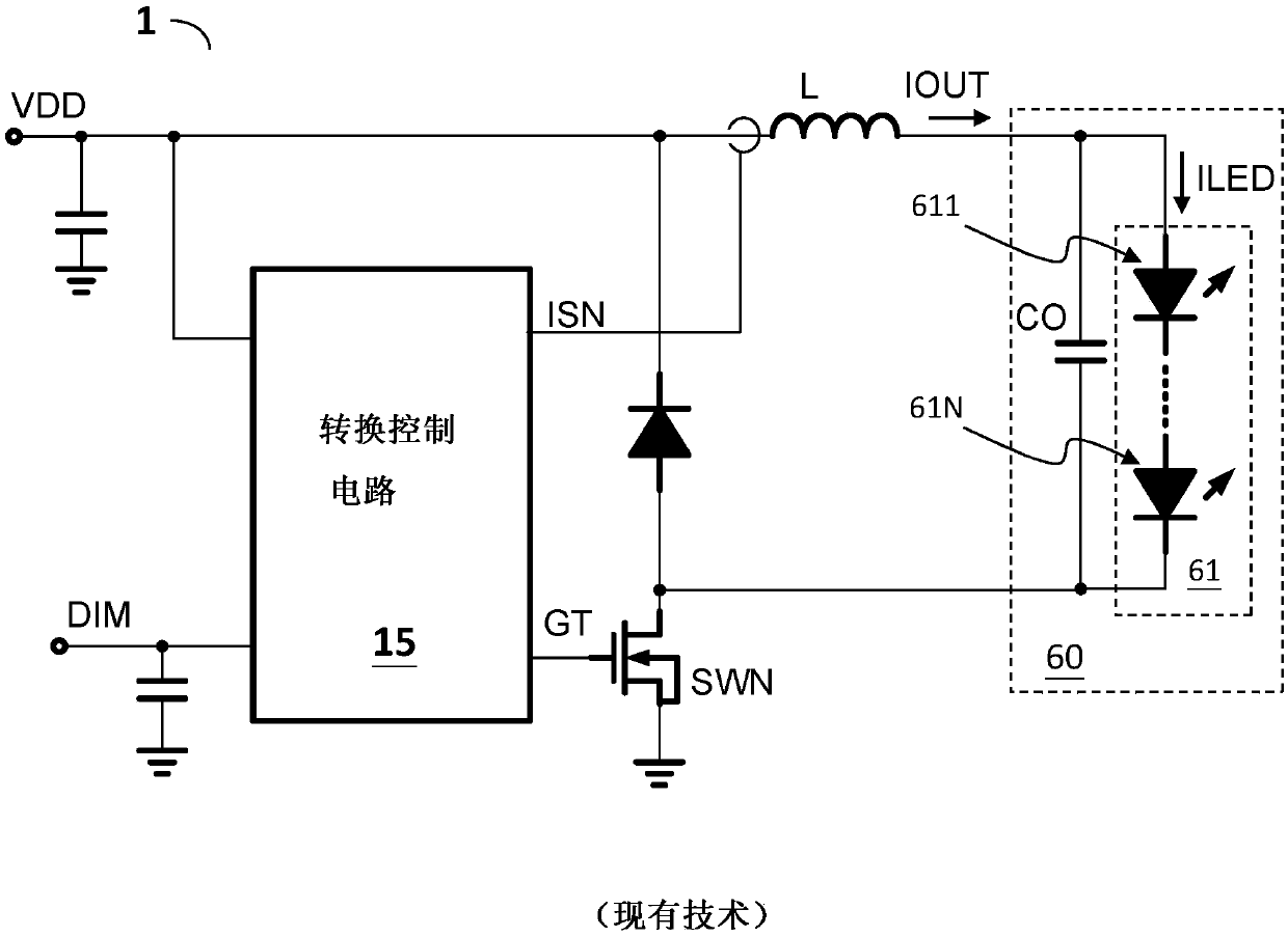
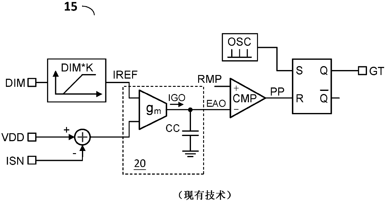
[0036] see Figures 5A-5B , shown in the figure is an embodiment of the light-emitting element driving device (light-emitting element driving device 5 ) of the present invention and an embodiment of the switching control circuit 10 therein. The light emitting device driving device 5 includes an inductor L, a power switch SWN, and a switching control circuit 10 . The power switch SWN is coupled to the inductor L for switching the inductor L to convert the input power VDD to generate an output current IOUT for driving the light-emitting device circuit 60 . The conversion control circuit 10 is used for switching the power switch SWN to generate the output current IOUT. In one embodiment, the li...


PUM


Abstract

The invention provides a light emitting device driver apparatus with a multiple dimming modes and a conversion control circuit thereof. The light emitting device driver apparatus includes: an inductor; a power switch which switches the inductor to convert an input power to an output current for driving a light emitting device circuit; and a conversion control circuit. When a dimming signal exceedsa first dimming threshold, a reference current signal is generated according to the dimming signal, and a switch control signal controls the power switch according to a first PWM signal, such that the output current corresponds to the level of the dimming signal. When the dimming signal does not exceed the first dimming threshold, the reference current signal is clamped to a level corresponding to the first dimming threshold, and a second PWM signal is generated according to the dimming signal, wherein the second PWM signal enables the first PWM signal to generate the switch control signal tocontrol the power switch.

Description

technical field [0001] The invention relates to a light-emitting element driving device, in particular to a light-emitting element driving device with multiple dimming modes. The present invention also relates to a conversion control circuit used in a light-emitting element driving device with multiple dimming modes. Background technique [0002] Figure 1A and 1B shows a prior art light-emitting element driving device (light-emitting element driving device 1) and its switching control circuit (switching control circuit 15), the light-emitting element driving device 1 uses the switching control circuit 15 to control the power switch SWN to switch the inductance L The input power VDD is converted to generate an output current IOUT for driving the light-emitting device circuit 60 . Figure 1B Among them, the dimming control circuit 50 is used to receive the analog (continuous) dimming signal DIM to generate the reference current signal IREF, and the error amplifier circuit 2...

Claims


Application Information

Patent Timeline
IPC IPC(8): H05B33/08H05B44/00
Inventor 杨孟勋林琦修邱韦铭
Owner RICHTEK TECH
Why Eureka
Try Eureka