

An air inflation free tire structure
A non-pneumatic tire and wheel hub technology, applied in the direction of wheels, highly elastic wheels, vehicle parts, etc., can solve the problems of destroying the structural strength of tires and blowing out tires, and achieve the effects of convenient processing and molding, improved safety, and avoiding blowouts
Inactive Publication Date: 2019-09-13
BEIJING RES & DESIGN INST OF RUBBER IND
View PDF9 Cites 1 Cited by
- Summary
- Abstract
- Description
- Claims
- Application Information
AI Technical Summary
Problems solved by technology
If heat builds up to the point where it changes the chemical properties of the rubber, it can destroy the tire's structural strength, causing a blowout
Method used
View moreImage
Smart ImageViewing Examples

Examples
Embodiment Construction
[0010] The present invention will be described in detail below in conjunction with the accompanying drawings and specific embodiments.
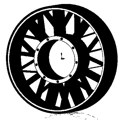
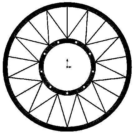
[0011] Such as figure 1 with figure 2 As shown, the non-pneumatic tire structure proposed by the present invention mainly includes an inner ring connected to the hub, an outer ring connected to the tread rubber, and an N-like elastomer connected to the outside of the inner ring.
[0012] The type N includes many elastomeric spokes along the radial direction of the tire, and the two spoke widths between the radial spokes each account for half of the radial spoke width, and are connected to the inner and outer rings by staggering on two sides.
Login to View More PUM
 Abstract
The invention relates to an air inflation free tire structure comprising an inner ring connected to a hub, an outer ring connected to tread rubber and an N-type elastomer connected to the inner and outer rings to form an annular air inflation free tire. The N-type elastomer comprises a plurality of elastomeric spokes in the radial direction of the tire, and the widths of the two spokes between theradial spokes respectively occupy half of the width of the radial spokes. The elastomeric spokes are staggered on both sides to be connected to the inner and outer rings. The air inflation free tirecan reduce tire weight and rolling resistance and prevent the occurrence of puncture.
Description
technical field [0001] The invention belongs to the technical field of auto parts, and relates to a non-pneumatic tire, in particular to a structure of a non-pneumatic tire. Background technique [0002] At present, due to structural limitations, there is a very important risk of pneumatic rubber tires, which is tire blowout. When a pneumatic tire is running on the road, due to rolling deformation, it is easy to generate a lot of heat in the tread, shoulder and sidewall, and rubber is a poor conductor of heat, and the speed of heat generation is much faster than its dissipation speed. will accumulate inside the tire. If the heat builds up to the point where it changes the chemical properties of the rubber, it can destroy the tire's structural strength and cause a blowout. [0003] The non-inflatable tire, as the name suggests, does not need to inflate the tire, there is no internal air pressure, and the operation of the vehicle is supported by the structural strength of th...
Claims
Login to View More Application Information
Patent Timeline
 Patent Type & AuthorityApplications(China)
IPC IPC(8): B60B9/26
CPCB60B9/26
Inventor熊伟蔡庆徐立
OwnerBEIJING RES & DESIGN INST OF RUBBER IND