Electromagnetic eddy current braking device

A brake device and electromagnetic eddy current technology, which is applied in the direction of electric brake system, electric vehicle, asynchronous induction clutch/brake, etc., can solve the problem of reducing the friction coefficient of the contact surface between the magnetic track brake and the track, failing to meet the braking requirements, Non-adhesive braking and other issues, to achieve the effect of small space occupation, meeting braking requirements, and strong impact resistance

Pending Publication Date: 2019-09-24
YANGZHOU UNIV
View PDF0 Cites 5 Cited by
  • Summary
  • Abstract
  • Description
  • Claims
  • Application Information

AI Technical Summary

Problems solved by technology

The current technology can keep rail trains running at medium and low speeds, but when the trains are running at high speeds, only non-adhesive braking can be used
At present, the common non-adhesive brakes suitable for high-speed rail trains include eddy current brakes and magnetic rail brakes. However, while ensuring high-speed operation, the friction coefficient between the magnetic rail brake and the track contact surface is greatly reduced, resulting in braking force Obviously insufficient, so that the braking requirements cannot be met, so it is necessary to design a special braking device to meet the braking requirements of high-speed trains

Method used


Image

  • Electromagnetic eddy current braking device
  • Electromagnetic eddy current braking device
  • Electromagnetic eddy current braking device

Examples


Embodiment Construction

[0026] The present invention will be further described below in conjunction with accompanying drawing:

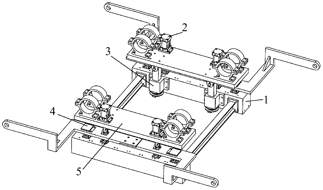
[0027] Such as figure 1 As shown, an electromagnetic eddy current braking device is composed of an excitation unit 1, a lifting device 2, a braking force transmission device 3, a gap adjustment device 4 and a support plate device 5; the excitation unit 1 is located in the braking device The lowermost end is movably connected with the lower end of the lifting device 2, the lifting device 2 is fixedly installed on the support plate device 5, the braking force transmission device 3 is installed on the inner side of the excitation unit 1, the upper end is hinged with the support plate device 5, and the lower end is connected with the support plate device 5. The excitation unit 1 is slidably connected, the gap adjustment device 4 is installed above the excitation unit 1, and is respectively connected to the train wheel shaft through the support frame 42, and the support plate de...


PUM


Abstract

The invention discloses an electromagnetic eddy current braking device, and belongs to the technical field of high speed train braking. The electromagnetic eddy current braking device is composed of a magnet exciting coil unit, lifting devices, braking force transferring devices, gap adjusting devices and supporting plate devices. According to the electromagnetic eddy current braking device, the structure of the device is novel, the operating principle is clear, the magnet exciting unit is utilized to provide stable and reliable braking force, and iron cores and magnet yokes adopt integrated modeling; the lifting devices are utilized to bear the resultant force of brake gravity and electromagnetic attraction, air cylinders have high impact resistance, and dual hinges enable pistons of the air cylinders to only bear the force in the direction perpendicular to a rail; the braking force transferring devices are utilized to transfer the braking force horizontally on the rail surface to a bogie, lifting and lowering of the brake are not affected, and supporting rod structures only bear the horizontal force and can move in the vertical direction freely; the gap adjusting devices are utilized to adjust the size of gaps, the space occupied by the gap adjusting devices is small, and the gap adjusting operation is easy; and the supporting plate devices are utilized to provide support for the lifting devices and the braking force transferring devices, and the whole device is safe and reliable.

Description

technical field [0001] The invention belongs to the technical field of high-speed train braking, and relates to an electromagnetic eddy current braking device, in particular to an electromagnetic eddy current braking device for high-speed train braking. Background technique [0002] At present, my country's railway transportation is developing rapidly, the speed of trains is gradually increasing, and the volume of train transportation is increasing day by day. The stability and safety of train operation has become the main research direction. The current technology can keep rail trains running at medium and low speeds, but when the trains are running at high speeds, only non-adhesive braking can be used. At present, the common non-adhesive brakes suitable for high-speed rail trains include eddy current brakes and magnetic rail brakes. However, while ensuring high-speed operation, the friction coefficient between the magnetic rail brake and the track contact surface is greatl...

Claims


Application Information

Patent Timeline
Patent Type & Authority Applications(China)
IPC IPC(8): B60L7/28H02K49/04
CPCB60L7/28B60L2200/26H02K49/04Y02T10/64
Inventor 张善文孔敏崔小龙缪宏徐志富张燕军徐帅刘思幸张剑峰高吉成
Owner YANGZHOU UNIV
Why Eureka
Try Eureka