A stack-type rotating electrostatic generator

A generator and electrostatic technology, applied in the direction of induction generators, etc., can solve the problems of easy damage of the nanostructure on the surface of the friction layer, warping of sector disks, and affecting power generation efficiency, etc., achieve light weight, realize collection and utilization, and simple structure Effect

Active Publication Date: 2021-02-02
NORTHWESTERN POLYTECHNICAL UNIV
View PDF4 Cites 0 Cited by
  • Summary
  • Abstract
  • Description
  • Claims
  • Application Information

AI Technical Summary

Problems solved by technology

However, because it is based on triboelectric power generation, the nanostructure on the surface of the friction layer is easily damaged, which affects the power generation efficiency; and the multi-layer stacking method proposed in this paper is a way in which the D-shaped shaft fits with the center hole of the sector disk, and there are no other positioning connectors , easy to loosen; and the distance between adjacent sector discs is controlled by screws and springs, which is prone to sector disc warping, and more stringent requirements will be put forward for the final package

Method used


Image

  • A stack-type rotating electrostatic generator
  • A stack-type rotating electrostatic generator
  • A stack-type rotating electrostatic generator

Examples


Embodiment 1

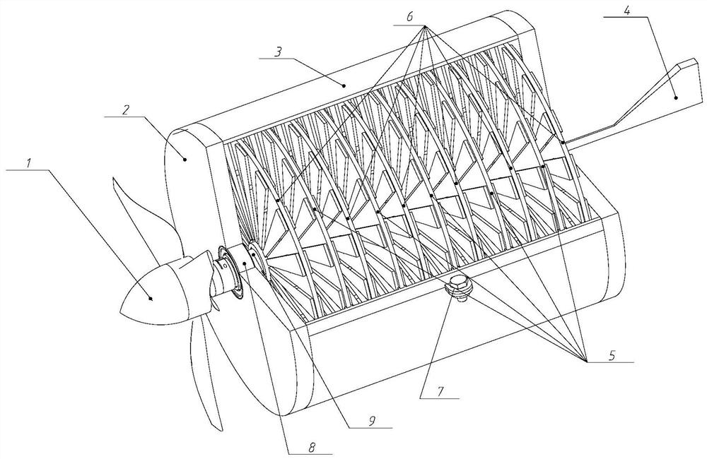
[0039] like figure 1 As shown, this embodiment provides a wind-induced stack-type rotating electrostatic generator, including: a power collection blade assembly 1, a bearing seat plate 2, a fixed cylinder 3, a tail 4, a moving disc 5, a static disc 6, a connection The screw assembly 7, the oil seal bearing 8, the rotating shaft 9; the fixed cylinder 3 is composed of two identical semi-cylindrical structures, which are fixed into an integral cylinder by the connecting screw assembly 7, which includes a hexagonal head bolt, a flat gasket, a hexagonal The head nut and the lugs set on the straight edge of the semi-cylindrical structure, among which, M3×8 bolts, M3 nuts and washers are selected; both ends of the fixed cylinder 3 are closed by the bearing seat plate 2, and the bearing seat plate 2 is acrylic The outer diameter is 95-110mm, the middle hole is 19mm in diameter, and the thickness is 5-8mm; 5 moving discs 5 and 5 static discs 6 are coaxially staggered and installed on t...

Embodiment 2

[0049] Figure 9 A schematic structural diagram of the second embodiment of the present invention is shown. The power collection assembly 1 is replaced by a number of turbine propellers, and the rest of the components are the same as the first embodiment. After adjusting the direction of the power collection assembly, it can rotate under the drive of water flow, and then drive the rotating shaft to rotate, so that the said The moving disc 5 and the stationary disc 6 form relative motion in the rotation direction of the rotating shaft, that is, the facing area between the electret and the working electrode changes periodically, so that the Charge recombination, output current to the external circuit, and realize the collection of water flow energy. It can be used for real-time measurement of environmental water flow, and the generated electricity can also be stored in the energy storage element.

Embodiment 3

[0051] Figure 10 A schematic structural diagram of the third embodiment of the present invention is shown. The power collection part 1 is replaced with a blade that can collect vertical wind power, and the other parts are the same as the first embodiment. The vertical wind blade does not need to face the wind when the wind direction changes. Compared with the first embodiment, the design and installation of the tail can be omitted. The structure is simplified, and the gyro force of the wind blade against the wind is also reduced. The mechanical energy in the environment is converted into power for driving the rotating shaft 9 to rotate, and the rest of the working principle is the same as the previous embodiment, and finally the utilization of wind energy is realized.

[0052] The stack-type rotating electrostatic generator of the present invention can expand the output by stacking a plurality of power generating units, thereby increasing the output power of the generator. ...


PUM


Abstract

The invention relates to a stacked rotary electrostatic generator, belonging to a micro energy system, comprising a power collection assembly, a bearing seat plate, a fixed cylinder, a moving disk assembly, a static disk, a connecting screw assembly, an oil seal bearing and a rotating shaft; the power collection assembly The component is fixed on the rotating shaft, and driven by external force, the rotating shaft and the moving disk assembly fixed on the rotating shaft are driven to rotate synchronously, so that the electret electrode on the moving disk and the working electrode on the static disk are positively aligned. Periodic changes in the area cause periodic changes in the capacitance value, thereby generating electrical signals and outputting them to external circuits. The output electric energy can be applied to the power supply of various wireless sensor nodes or as a real-time monitoring of the flow rate of the environmental fluid. Since the positive and negative electrets are arranged at equal intervals, the charging efficiency on the surface of the moving disk is greatly improved, and the output power of the generator is increased.

Description

technical field [0001] The invention belongs to the field of energy conversion of a micro-energy system, and in particular relates to a stack-type rotating electrostatic generator. Background technique [0002] With the wide application of portable electronic products in daily life, it is urgent to find a power supply method that is easy to combine with them and has high reliability. The method of harvesting existing mechanical energy from the environment has gradually become a power system solution for self-powered MEMS, which is also more conducive to further miniaturization of MEMS. It can convert the widely existing natural environment such as wind energy and hydraulic energy into rotational motion energy that can drive the generator to work. Under the same conditions, the electret generator has the characteristics of higher output power and lower operating frequency than the traditional electromagnetic generator. A three-dimensional stacked rotating electrostatic ener...

Claims


Application Information

Patent Timeline
Patent Type & Authority Patents(China)
IPC IPC(8): H02N1/08
CPCH02N1/08
Inventor 陶凯易海平张瑞荣申强杨扬常洪龙
Owner NORTHWESTERN POLYTECHNICAL UNIV
Why Eureka
Try Eureka