
Light-transmission rain-proof type shutter window
A technology of blinds and window frames, applied in the field of blinds, can solve problems such as single function of blinds, and achieve the effects of improving lighting capacity, maintaining indoor temperature, and preventing rain and snow from entering the room.
- Summary
- Abstract
- Description
- Claims
- Application Information
AI Technical Summary
Problems solved by technology
Method used
Image

Examples
Embodiment
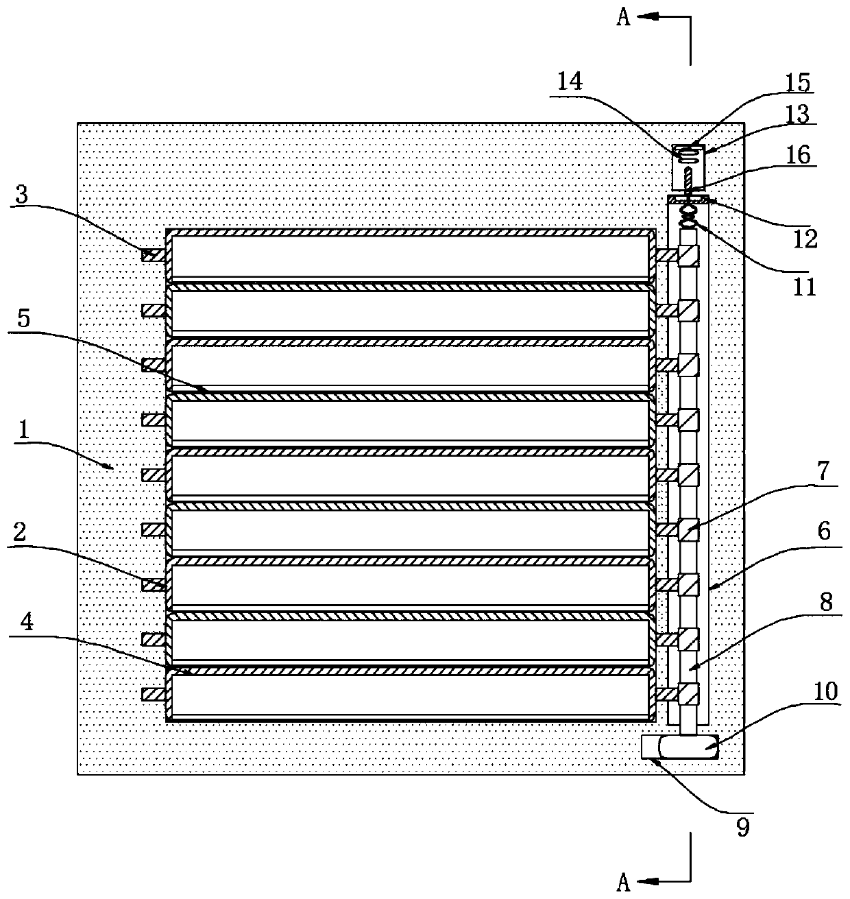
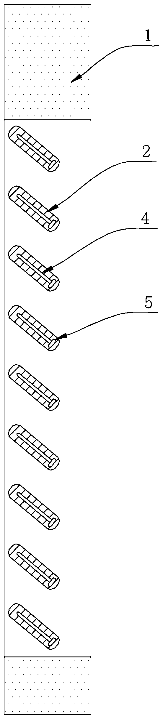
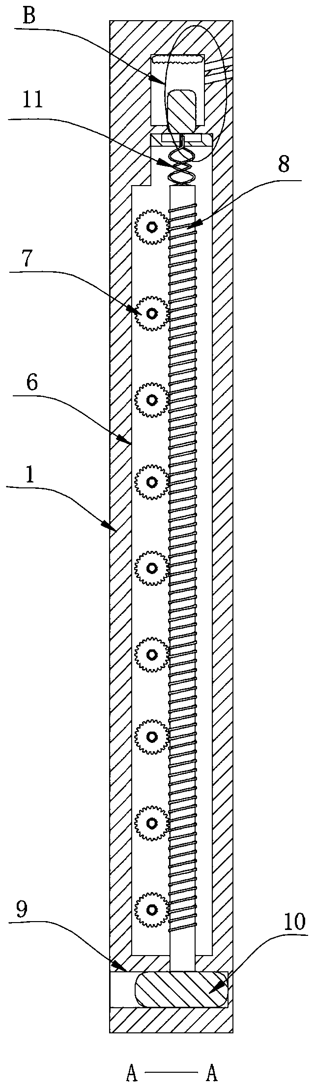
[0021] refer to Figure 1-4 , a light-transmitting and rain-proof shutter, comprising a window frame 1 and a plurality of rotating leaves 2, each rotating leaf 2 is connected to the inner wall of the window frame 1 through a rotating shaft 3 fixed at its two ends, and the side wall of the rotating leaf 2 Both of them are glued with sealing rubber strips, which maintain a good sealing effect when the two rotor blades 2 are in contact. The inside of the window frame 1 is provided with a control chamber 6 and a heating chamber 13. The bottom of the control chamber 6 is connected with a worm 8 through bearing rotation. One end of each rotor blade 2 close to the control cavity 6 runs through the inner wall of the window frame 1 and extends to the inside of the control cavity 6 and is welded with a worm wheel 7. A plurality of worm wheels 7 are meshed with the worm 8, and the upper end of the worm 8 is welded with a rotating metal 11, which rotates The upper end of the metal 11 is w...
PUM
 Abstract
Description
Claims
Application Information