A FFT-based distributed optical fiber vibration sensing positioning method and device

A distributed optical fiber and vibration sensing technology, which is applied to measurement devices, instruments, and the use of wave/particle radiation, etc., can solve the problems of low practicability, complex algorithm implementation, and increase the false alarm rate, so as to improve the accuracy of discrimination. , The effect of suppressing high false alarm rate and reducing false alarm rate

Active Publication Date: 2021-06-11
郑州信大先进技术研究院
View PDF17 Cites 0 Cited by
  • Summary
  • Abstract
  • Description
  • Claims
  • Application Information

AI Technical Summary

Problems solved by technology

When making early warning judgments in practical applications, the vibration signals that really need to be monitored are overwhelmed by other vibration signals around (caused by the environment), which will bring great trouble to the determination of the real vibration position and cause a high false alarm rate.
At this stage, the method of dynamic threshold and pattern recognition is mainly used to solve this problem: dynamic threshold can reduce the false alarm rate to a certain extent, but it will inevitably increase the false alarm rate; pattern recognition can judge the type of vibration, but the algorithm realizes complex, low availability

Method used


Image

  • A FFT-based distributed optical fiber vibration sensing positioning method and device
  • A FFT-based distributed optical fiber vibration sensing positioning method and device
  • A FFT-based distributed optical fiber vibration sensing positioning method and device

Examples


Embodiment Construction

[0033] The technical solutions of the present invention will be described in further detail below through specific implementation methods.

[0034] The distributed optical fiber vibration monitoring system mainly includes two monitoring systems based on intensity demodulation and phase demodulation. Both systems can use the positioning method described in the present invention when positioning the vibration position. In this embodiment, the phase demodulation system ( φ-OTDR) as an example to introduce the positioning method described in the present invention in detail.

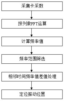
[0035] like figure 1 As shown, a FFT-based distributed optical fiber vibration sensing positioning method includes the following steps:

[0036] S1, collecting multiple pulse data strings output by the photodetector, where the pulse data strings are a collection of several return data collected under a single emission pulse.

[0037] The number of the return data corresponds to the propagation distance of t...


PUM


Abstract

The present invention provides an FFT-based distributed optical fiber vibration sensing positioning method. By collecting the Rayleigh backscattering signals of multiple pulses, FFT is performed on the signals accumulated at each position. According to the amplitude-frequency characteristics at the position, Determine the frequency of the vibration signal at this position, use the frequency as the judgment condition to screen, and process the frequency results that meet the judgment conditions with the difference at the corresponding position at adjacent times, and accurately identify the real and effective vibration position when the optical cable is affected by the external environment. The present invention also provides an FFT-based distributed optical fiber vibration sensing and positioning device, which is used to implement the aforementioned positioning method. The invention judges the vibration position by combining the vibration frequency characteristics of different vibration forms and the real vibration suddenness characteristics, the algorithm is simple to realize, and has good engineering practicability.

Description

technical field [0001] The invention relates to the field of distributed optical fiber vibration sensing, in particular to an FFT-based distributed optical fiber vibration sensing positioning method and device. Background technique [0002] The distributed optical fiber vibration sensing system is composed of long-distance distributed detection optical fiber arranged at the front end, optical fiber demodulation host, and host computer software. The system uses a laser source and an acousto-optic modulator to continuously inject pulsed light into the detection fiber, and receives the back Rayleigh scattered light containing the vibration or sound signal after the detection of the vibration or sound wave signal in the sensing fiber. The sensor and acquisition card transmit the signal to the host computer for data processing, and finally demodulate the vibration information. The distributed optical fiber vibration sensing system performs all-day, all-weather long-distance cont...

Claims


Application Information

Patent Timeline
Patent Type & Authority Patents(China)
IPC IPC(8): G01H9/00
CPCG01H9/004
Inventor 邵佳杨纳川刘正堂牛原野袁航王永华赵翠霞
Owner 郑州信大先进技术研究院
Why Eureka
Try Eureka