Steel wire twisting mechanism for steel wire rust removing machine

A derusting machine and steel wire technology, which is applied to the parts of grinding machine tools, grinding racks, devices for fixing grinding wheels, etc., can solve the problems of unclean treatment, small friction, and dead angle of rust removal, etc., and achieve flexible rotation, Effect of reducing frictional resistance and preventing wear

Inactive Publication Date: 2020-05-05
ZHEJIANG MOPPER ENVIRONMENTAL TECH CO LTD
View PDF0 Cites 6 Cited by
  • Summary
  • Abstract
  • Description
  • Claims
  • Application Information

AI Technical Summary

Problems solved by technology

[0003] The steel wire derusting machine of prior art generally adopts derusting roller to the surface of steel wire to derust, and the derusting roller of this steel wire derusting machine is installed horizontally, can only carry out derusting to steel wire from the upper and lower parts of steel wire, because The cross-section of the steel wire is circular, the closer to the two sides of the steel wire, the smaller the pressure of the grinding roller on the phosphorus breaking roller on the steel wire, and the smaller the frictional force. The areas of about 5° on both sides of the steel wire are unclean. There is a dead angle in rust removal

Method used


Image

  • Steel wire twisting mechanism for steel wire rust removing machine
  • Steel wire twisting mechanism for steel wire rust removing machine
  • Steel wire twisting mechanism for steel wire rust removing machine

Examples


Embodiment Construction

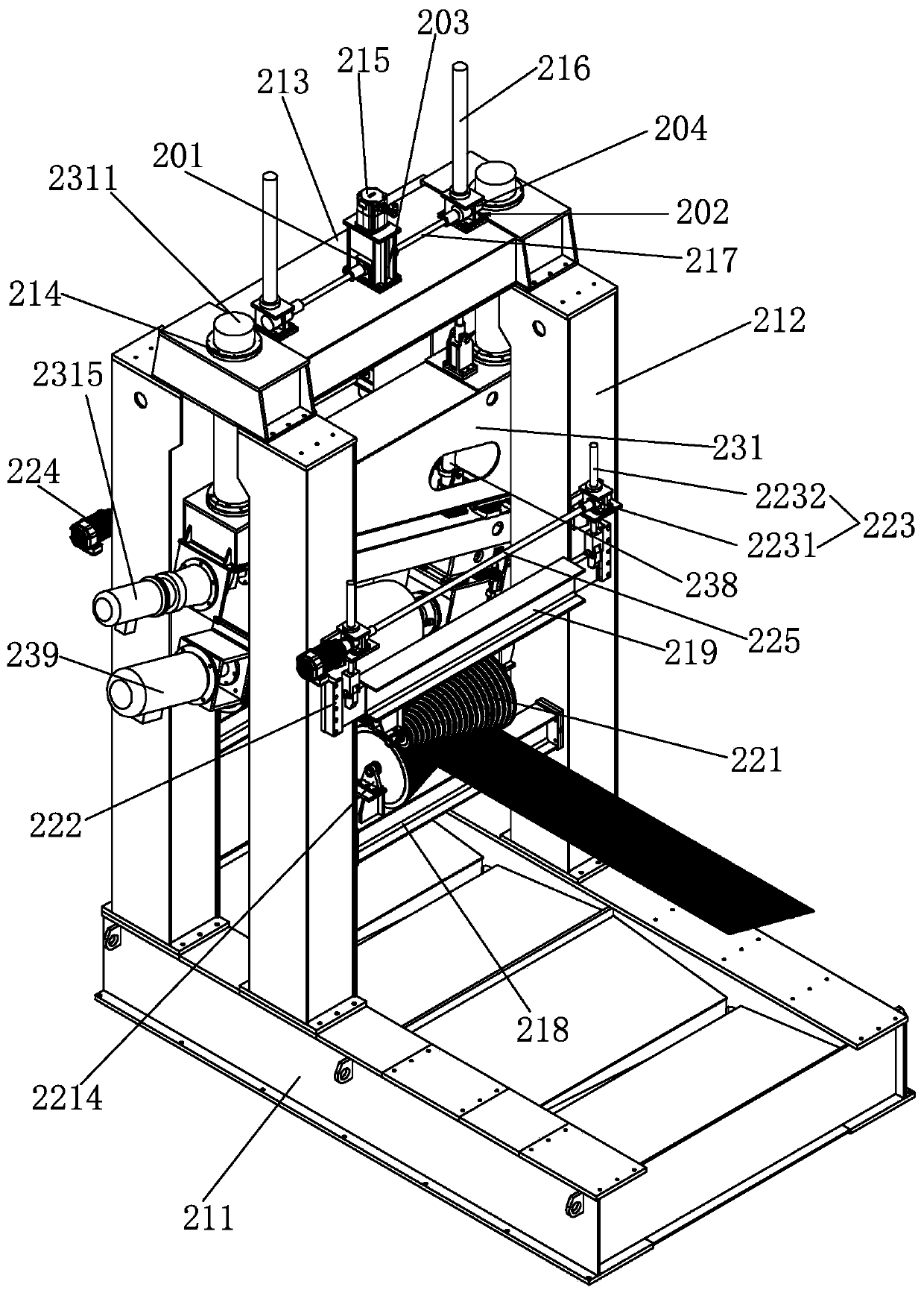
[0039] The specific embodiments of the present invention will be described in detail below in conjunction with the drawings. In this embodiment, front and back are defined by the direction of wire travel, and the sides of the direction of wire travel are defined as left and right. The side close to the wire is defined as the inner side, and the side far from the wire is defined as the outer side.

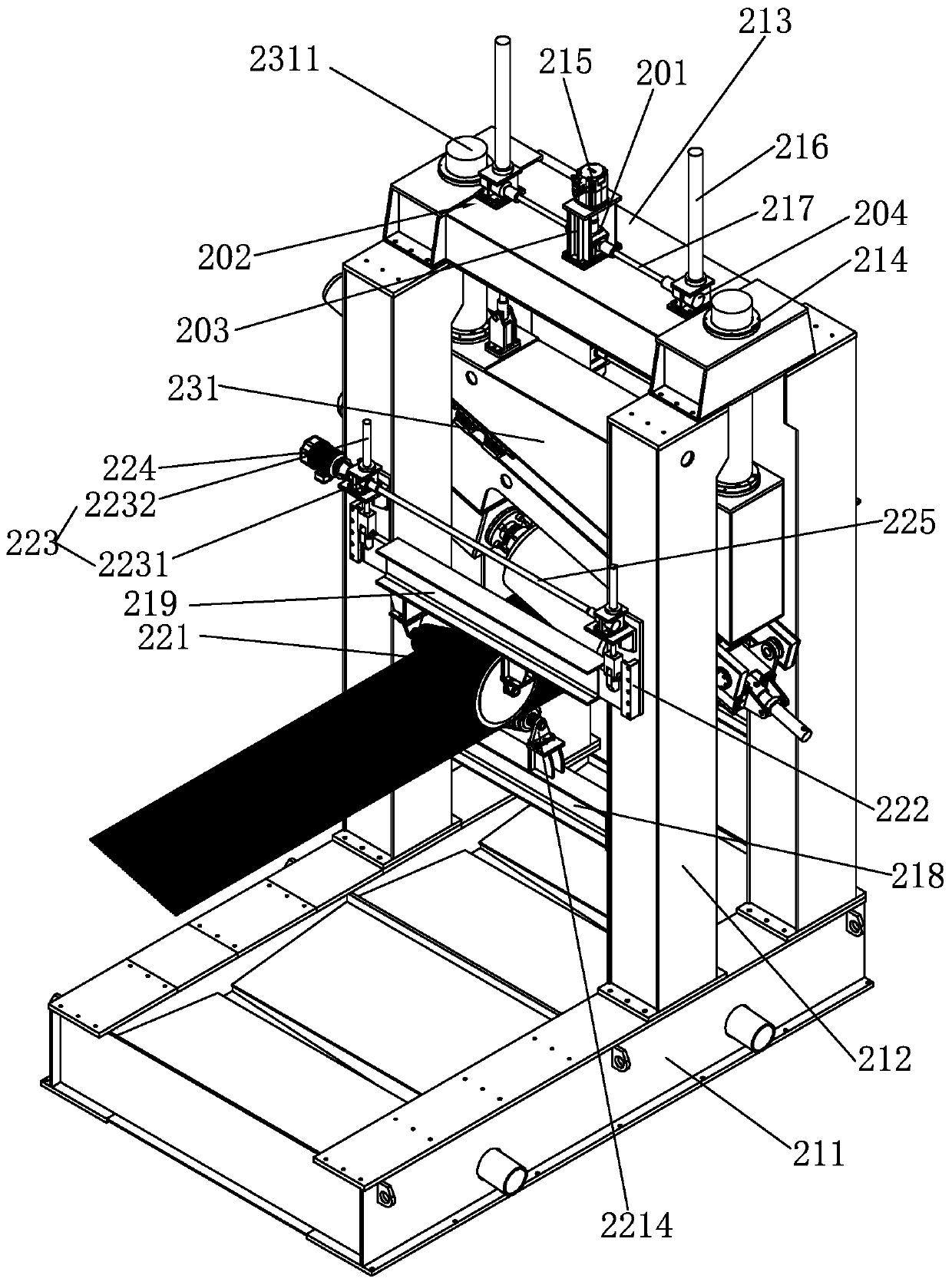
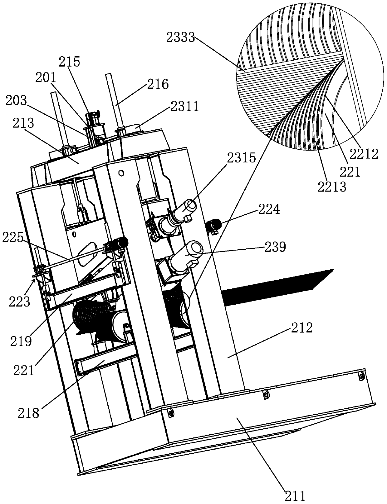
[0040] Such as Figure 1 ~ Figure 6 As shown, the steel wire rust removing machine includes a rust removing frame 21, a steel wire torsion mechanism 22, and a steel wire rust removing mechanism 23. There are two steel wire torsion mechanisms 22, and the two steel wire torsion mechanisms 22 are respectively arranged in the rust removing frame 21. At the steel wire entrance and the steel wire exit, the steel wire rust removing mechanism 23 is arranged between the two steel wire torsion mechanisms 22 on the rust removing frame 21.

[0041] Such as Figure 1 ~ Figure 6 As shown, the derustin...


PUM


Abstract

The invention relates to a steel wire twisting mechanism for a steel wire rust removing machine. The steel wire twisting mechanism is installed on the steel wire inlet side of the steel wire rust removing machine, and comprises a lower cross beam and an upper cross beam which are horizontally installed at the steel wire inlet end of the rust removing machine, wherein at least one of the lower cross beam and the upper cross beam can move up and down in the vertical direction and can be fixed after being lifted; a conical steering roller is installed on each of the lower cross beam and the uppercross beam, the conical steering roller of the lower cross beam and the conical steering roller of the upper cross beam are oppositely installed, and steering roller shafts of the two steering rollers are kept in a horizontal state; a plurality of guide grooves are uniformly formed in the roller surfaces of the two steering rollers, and after the roller surfaces of the two steering rollers are attached, the guide grooves of the two steering rollers are matched in a one-to-one mode to form gaps for allowing a steel wire to pass therethrough. The steel wire twisting mechanism is arranged, so that the steel wire can be twisted, places where the steel wire originally is not be brushed are to be brushed cleanly after the steel wire is twisted, then the steel wire is cleaned in all directions through the flat brush in the following working procedure, and the rust removing dead corner does not exist.

Description

Technical field [0001] The invention belongs to the technical field of metal surface treatment, and particularly relates to a steel wire twisting mechanism of a steel wire rust remover. Background technique [0002] It often takes a period of time before the steel wire is produced to actual use. During this time, due to various reasons, the surface of the steel wire will rust, which affects the actual use. Therefore, the surface of the steel wire needs to be derusted before using the rusty steel wire. deal with. [0003] The prior art steel wire rust remover generally uses a phosphorus-breaking roller to derust the surface of the steel wire. The phosphorus-breaking roller of this steel wire rust remover is installed horizontally and can only remove rust from the upper and lower parts of the steel wire. The steel wire has a circular cross-section. The closer to both sides of the steel wire, the lower the pressure of the grinding roller on the phosphorus-breaking roller on the steel...

Claims


Application Information

Patent Timeline
Patent Type & Authority Applications(China)
IPC IPC(8): B24B27/033B24B27/00B24B41/02B24B45/00B24B47/06B24B55/00
CPCB24B27/0076B24B27/033B24B41/02B24B45/006B24B47/06B24B55/00
Inventor 傅如学
Owner ZHEJIANG MOPPER ENVIRONMENTAL TECH CO LTD
Why Eureka
Try Eureka