Shuttle machine speed changing mechanism

A speed change mechanism and shuttle machine technology, which is applied in the direction of mechanical equipment, gear transmission devices, and components with teeth, etc., can solve the problems of excessive volume and weight, achieve reduced occupied volume and weight, improve operational safety performance, and reduce occupancy volume effect

Inactive Publication Date: 2020-05-22
GUANGDONG INTELLIGENCE LOGISTICS CO LTD
View PDF0 Cites 0 Cited by
  • Summary
  • Abstract
  • Description
  • Claims
  • Application Information

AI Technical Summary

Problems solved by technology

[0004] To sum up, the shuttle must have a transmission mechanism with gear shifting to better utilize different speeds to achieve the purpose of adapting to different terrains, but mo

Method used


Image

  • Shuttle machine speed changing mechanism
  • Shuttle machine speed changing mechanism
  • Shuttle machine speed changing mechanism

Examples


Embodiment 1

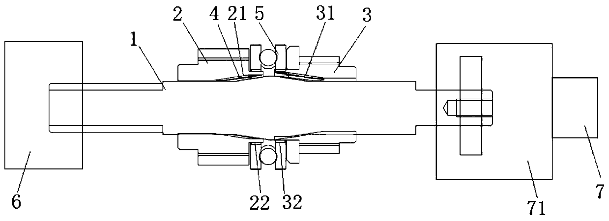
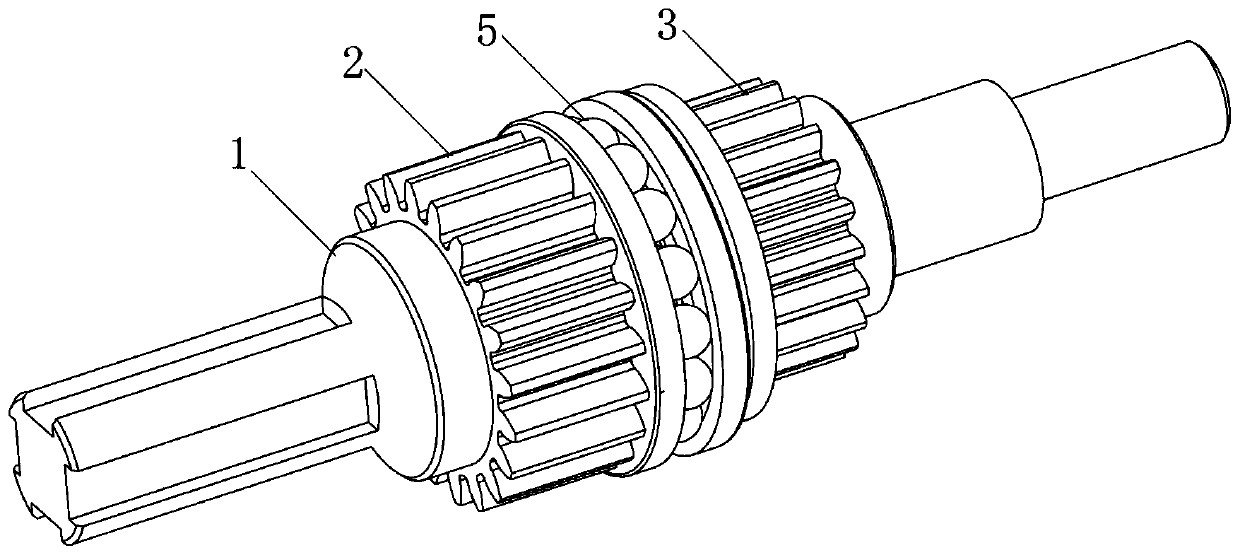
[0032] See figure 1 with figure 2 As shown, the shuttle speed change mechanism of the present invention is schematically shown, which includes a shift lever 1, a first gear 2 and a second gear 3, wherein the number of teeth of the first gear 2 and the second gear 3 are different and It is sleeved on the shift rod 1, and the outer circumference of the shift rod 1 is axially provided with a tooth set 4, and the tooth set 4 is located between the first gear 2 and the second gear 3. What is important is that the The inside of the first gear 2 is provided with a first tooth groove 21, the inside of the second gear 3 is provided with a second tooth groove 31, and the first tooth groove 21 is used to communicate with the first end of the tooth set 4 ( figure 1 The left end of the middle tooth group 4) is mated and plugged in, and the second tooth groove 31 is used to connect with the second end of the tooth group 4 ( figure 1 The right end of the middle tooth group 4) is mated and...

Embodiment 2

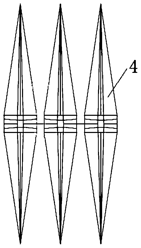
[0039] See Figure 5 As shown, the difference between the shift lever 1 in this embodiment and the first embodiment is that the tooth surfaces of the first helical teeth 41 and the second helical teeth 42 are arc-shaped, which is beneficial to the first helical teeth 41 and the second helical teeth. The helical teeth 42 enter the corresponding tooth slots more smoothly, avoiding the jamming phenomenon of gear shifting, and even the tip of the helical teeth and the tooth slots are pushed against each other when shifting gears, which affects the life of the helical teeth and the tooth slots. In this way, the tooth surfaces of the helical teeth are arranged in an arc shape, which can further improve the smoothness of shifting.

[0040] Preferably, in this embodiment, see Figure 4 As shown, the inclination angle α of the first helical teeth 41 ranges from 3-30°, and the inclination angle α of the second helical teeth 42 ranges from 3-30°. For the service life of the groove, pre...


PUM


Abstract

The invention relates to the field of cableway transportation equipment, and particularly discloses a shuttle machine speed changing mechanism. The shuttle machine speed changing mechanism comprises agear shifting rod, a first gear and a second gear, and the first gear and the second gear are arranged on the gear shifting rod in a sleeving mode and have different tooth numbers; a gear set positioned between the first gear and the second gear is axially arranged on the periphery of the gear shifting rod, first tooth grooves matched and connected with the first end of the gear set in an inserting mode are formed in the first gear, and second tooth grooves matched and connected with the second end of the gear set in an inserting mode are formed in the second gear; and the gear shift rod axially moves back and forth to enable the first end of the gear set to be inserted into the first gear grooves or enable the second end of the gear set to be inserted into the second gear grooves. The shuttle machine speed change mechanism is simple and practical in structure, has a multi-gear structure, can realize speed change control over a shuttle machine, is favorable for adapting to different terrain changes, and improves operation safety of the shuttle machine.

Description

technical field [0001] The invention relates to the technical field of cableway transportation equipment, in particular to a speed change mechanism of a shuttle. Background technique [0002] The use of ropeways to transport goods is a traditional logistics transportation method, which is still used in some occasions today. The use of shuttles to transport goods on ropeways is an improvement over traditional ropeway systems, which helps to transport goods to different destinations more quickly and efficiently. The current shuttle machine is usually composed of a control assembly, a drive mechanism, and a boom mechanism connecting the control assembly and the drive mechanism, wherein the control assembly can control the drive mechanism so that the drive mechanism drives the shuttle machine to travel along the cableway. [0003] Different from the traditional technology, the cableway is not only a single straight cableway, but the cableway needs to turn under different terrai...

Claims


Application Information

Patent Timeline
IPC IPC(8): F16H3/20F16H63/30
CPCF16H3/20F16H63/30
Inventor 马亚胜张旭耀黎树中
Owner GUANGDONG INTELLIGENCE LOGISTICS CO LTD
Why Eureka
Try Eureka