Suction cup bowl taking device with accurate locking function

A suction cup and functional technology, which is applied in the field of suction cup taking device, can solve the problems of unstable clamping, damage to the bowl, inability to fuse, etc., to achieve good suction freedom and precise control, the center of rotation is concentrated and stable, and the horizontal rotation radius is small. Effect

Active Publication Date: 2020-06-23
北京快端科技有限公司
View PDF6 Cites 0 Cited by
  • Summary
  • Abstract
  • Description
  • Claims
  • Application Information

AI Technical Summary

Problems solved by technology

There are many types of bowls on the market, and the styles are not unique. Due to the constraints of existing technologies, there are currently two main ways to take bowls in the catering industry: one is manual bowl picking, which can adapt to various bowls because of human participation. Bowl picking, but the bowl picking efficiency is low, the accuracy cannot be guaranteed, there are health risks, and it cannot be fully integrated with automatic cooking equipment; the other is automatic mechanical bowl picking, which is mainly for bowls with convex edges. , use the expansion fixture to clamp the convex edge, and then lift the bowl and move it to the designated position, but in this way of taking the bowl, the bowl taking fixture is in rigid contact with the bowl, which may damage the bowl, and the bowl taking fixture needs to be expanded and then clamped Take the operation space, and the bowl taking fixture is the position of the bowl mouth when lifting the bowl. The bowl may be shifted due to unstable clamping during the picking or moving process, resulting in the inability to guarantee the accuracy of the subsequent bowl placement. In addition, using this bowl picking Placement can only be adapted to bowls with a convex edge at the mouth of the bowl. If the shape of the bowl is different, it is necessary to replace the bowl taking fixture, which will undoubtedly increase the cost of use

Method used


Image

  • Suction cup bowl taking device with accurate locking function
  • Suction cup bowl taking device with accurate locking function
  • Suction cup bowl taking device with accurate locking function

Examples


Embodiment Construction

[0021] The technical solutions of the present invention will be further described below in conjunction with the accompanying drawings and through specific implementation methods.

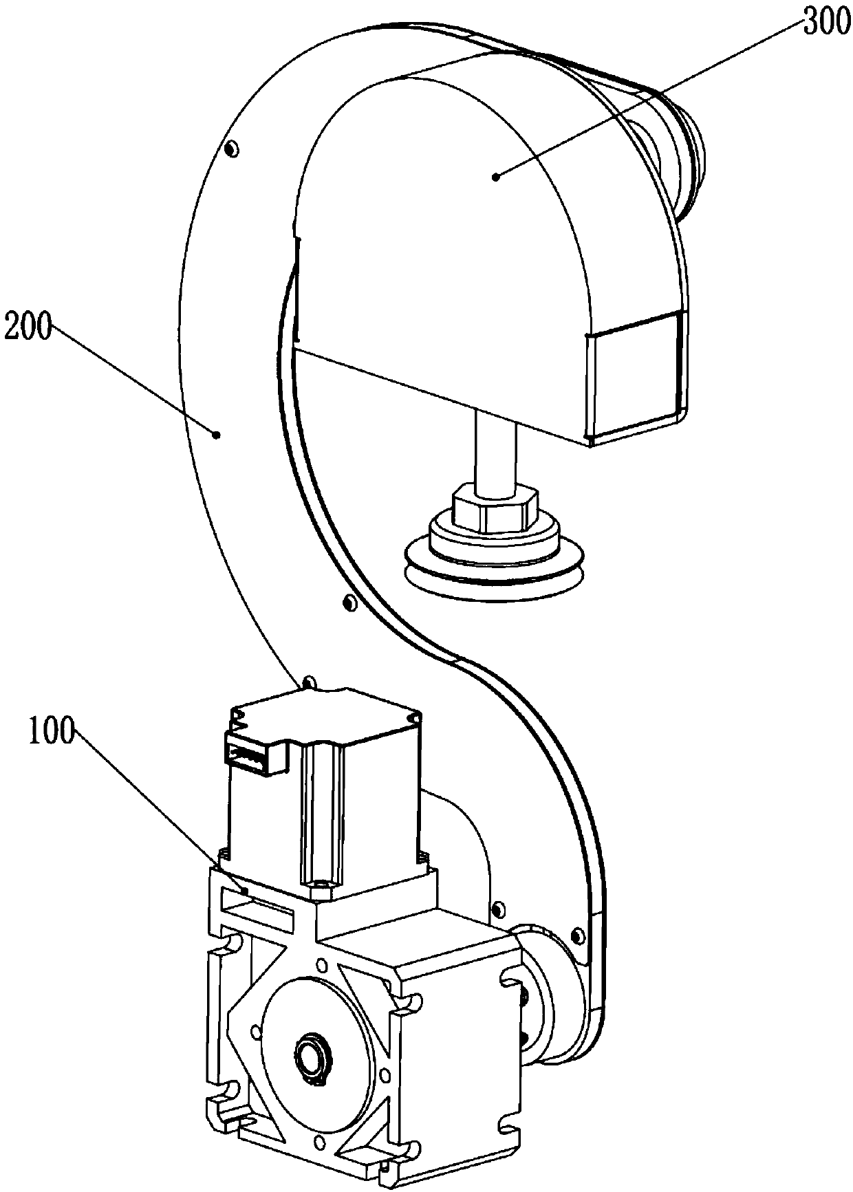
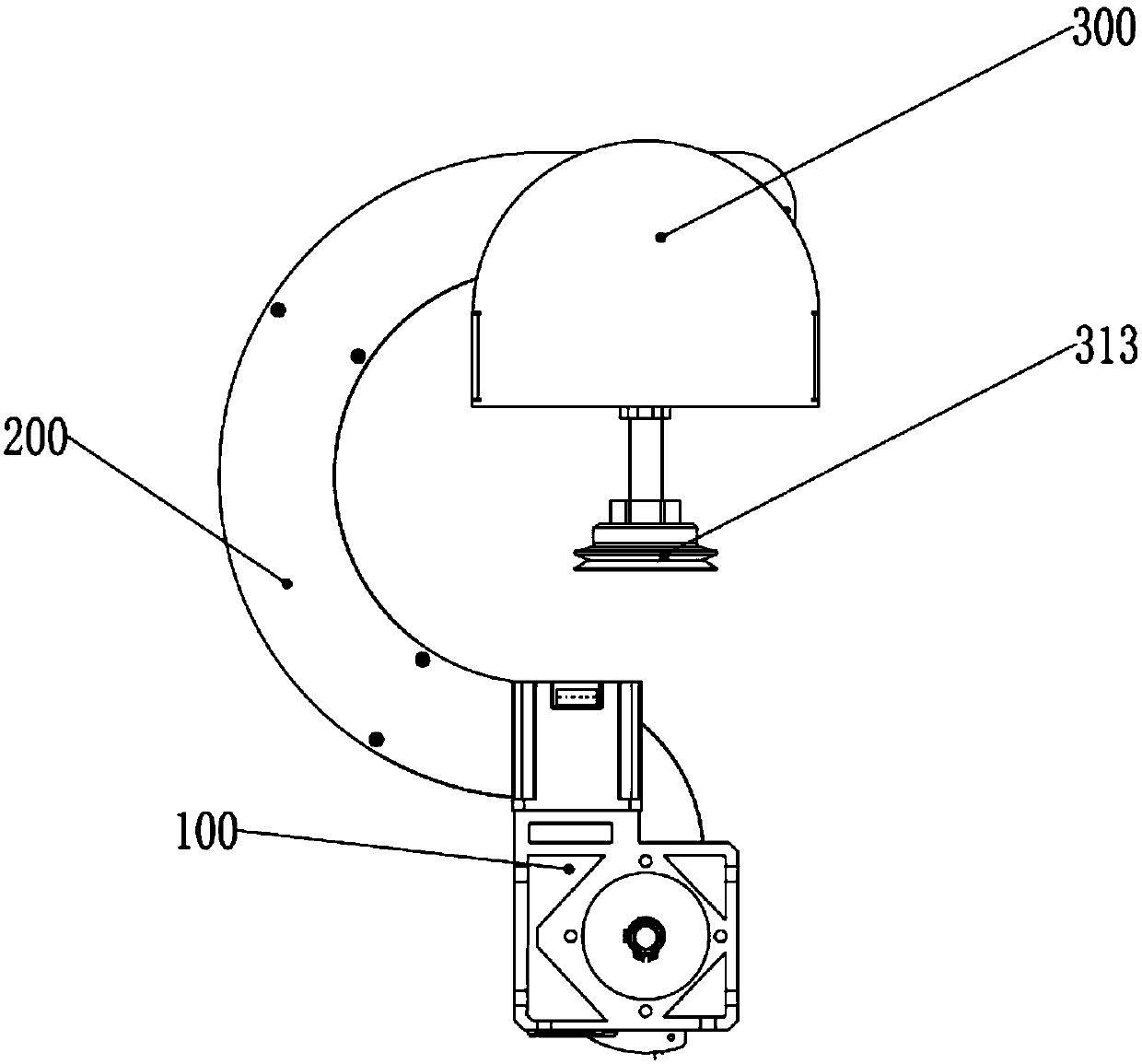
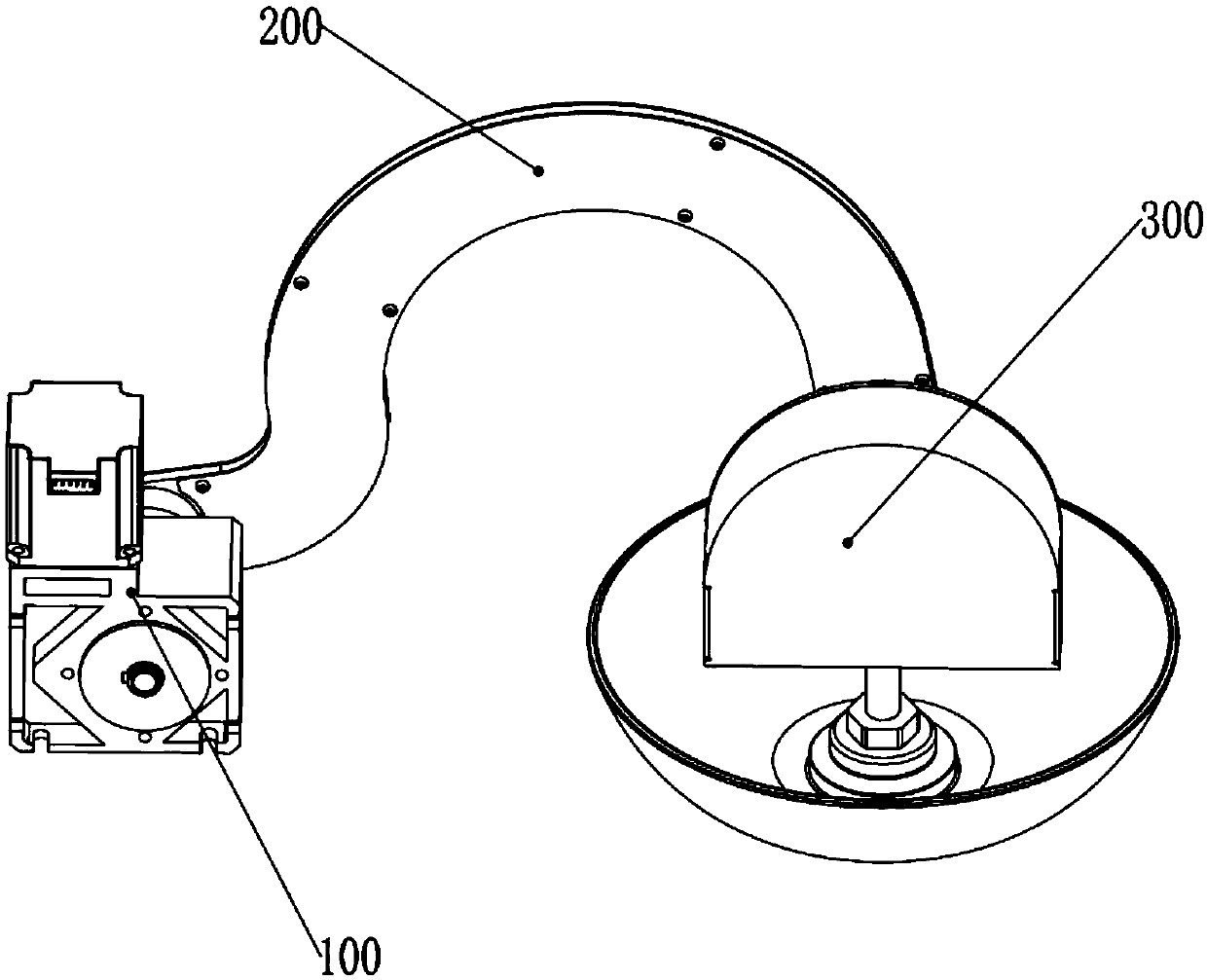
[0022] Such as Figure 1-4 As shown, a sucker bowl picking device with a precise locking function includes: a control box assembly 300, a swing arm assembly 200, and a motor assembly 100; the swing arm assembly 200 includes a swing arm body 210, and the swing arm The lower end of the body 210 is a driving section 211, and the upper end is a driven section 212; the driven section 212 is provided with a swing bearing 214; the motor assembly 100 is provided with a swing motor 110; the control box assembly 300 includes: a control box shell 310, a swing shaft 311, a vacuum pump 312 and a suction cup operating end; one end of the swing shaft 311 is connected to one side of the control housing, and the other end passes through the swing bearing 214 transversely; one end of the suction cup operating end is ...


PUM


Abstract

The invention relates to the technical field of kitchen equipment, in particular to a suction cup bowl taking device with laser detection control. The suction cup bowl taking device comprises a control box assembly, a swing arm assembly, an electric mortise lock and a motor assembly; the swing arm assembly comprises a swing arm body, the control box assembly comprises a control box shell, a swingrotating shaft, a vacuum pump, a suction cup and a laser ranging controller, the control box assembly can swing relative to the swing arm assembly; and the vacuum pump communicates with the sucking cup through an air pipe. The suction cup bowl taking device has a larger suction range, a small horizontal rotation radius and a concentrated and more stable rotation gravity center, the control box assembly can swing within a certain range to cater to inclined bowls, and the laser ranging controller and the electric mortise lock enable the swing controllability of the control box to be higher, so that the suction cup bowl taking device has the good suction freedom degree and accurate controllability, the bowl suction operation is more flexible and rapid, and bowl suction and moving are more accurate and stable.

Description

technical field [0001] The invention relates to the technical field of kitchen equipment, in particular to a sucker bowl picking device with a precise locking function. Background technique [0002] Bowls used to hold food in the catering industry are indispensable, and in catering places with a large number of people or catering equipment that automatically cooks and sells food, the amount of bowls will be larger, and it is necessary to adjust the speed of taking bowls, Accuracy and stability requirements are high. There are many types of bowls on the market, and the styles are not unique. Due to the constraints of existing technologies, there are currently two main ways to take bowls in the catering industry: one is manual bowl picking, which can adapt to various bowls because of human participation. Bowl picking, but the bowl picking efficiency is low, the accuracy cannot be guaranteed, there are health risks, and it cannot be fully integrated with automatic cooking equi...

Claims


Application Information

Patent Timeline
Patent Type & Authority Applications(China)
IPC IPC(8): B65G47/91G07F13/10
CPCB65G47/914B65G47/917G07F13/10B65G2201/0235
Inventor 李萧萧易君阳张京辉王尧
Owner 北京快端科技有限公司
Why Eureka
Try Eureka