Full-automatic stacking device for sintered bricks

A stacking device and sintered brick technology, applied in the field of sintered bricks, can solve the problem of occupying the horizontal space of the workshop, and achieve the effects of close connection between front and rear, high degree of automation and high linkage.

Inactive Publication Date: 2020-12-15
李兵
View PDF0 Cites 0 Cited by
  • Summary
  • Abstract
  • Description
  • Claims
  • Application Information

AI Technical Summary

Problems solved by technology

[0004] However, in the actual use process, the inventor found that when working in multi-layer stacking, the workbench will not fall naturally, and at the same time, when working in multiple stacks along the horizontal direction, the problem of occupying the horizontal space of the workshop

Method used


Image

  • Full-automatic stacking device for sintered bricks
  • Full-automatic stacking device for sintered bricks
  • Full-automatic stacking device for sintered bricks

Examples


Embodiment 1

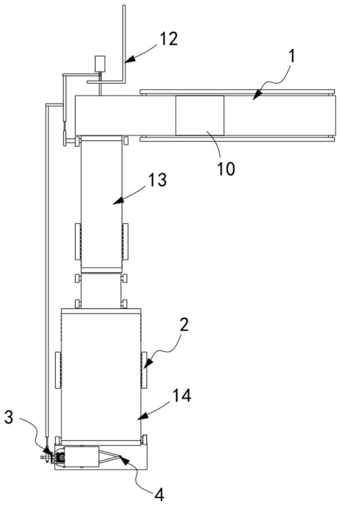
[0046] Such as figure 1 As shown, a fully automatic stacking device for sintered bricks, including:

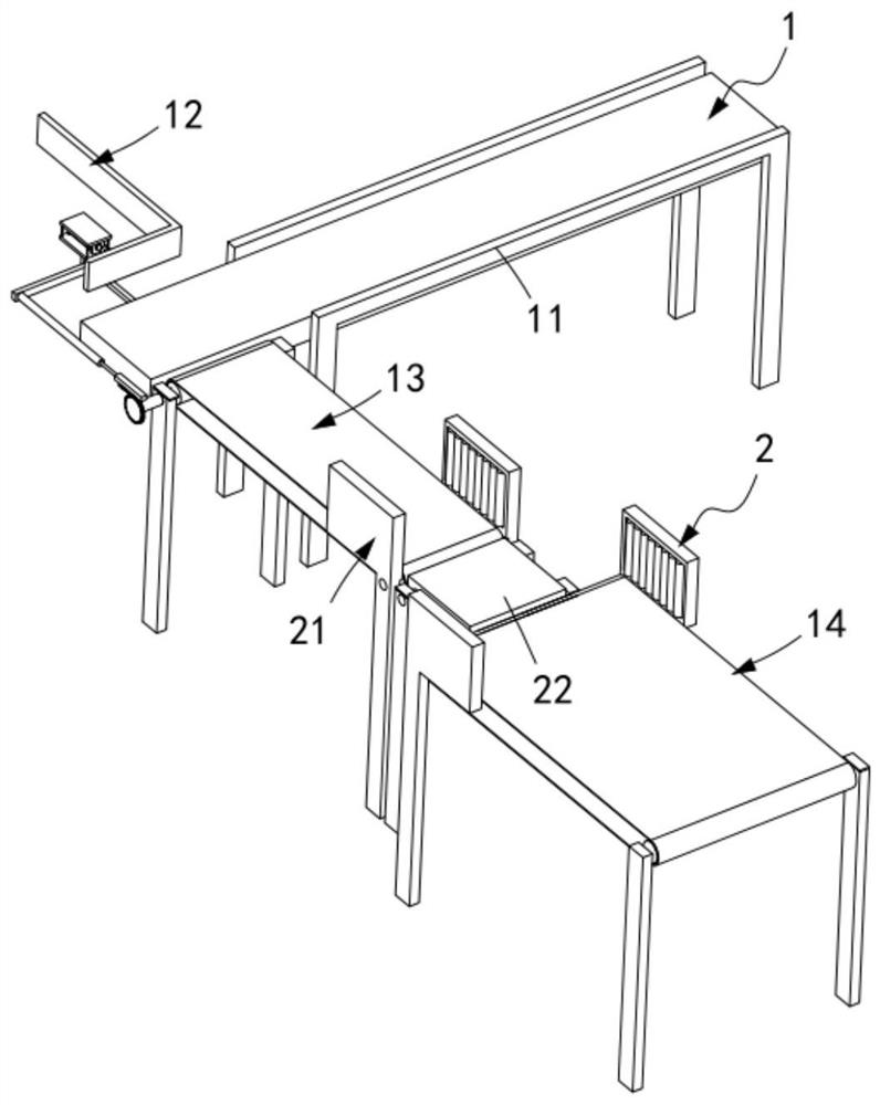
[0047] The transmission mechanism 1 is used to transport the sintered bricks 10, which includes a frame 11, a horizontal push assembly 12 arranged on the frame 11, a first A transmission component 13 and a second transmission component 14 located on one side of the first transmission component 13;

[0048] A grinding mechanism 2, the grinding mechanism 2 is located between the first transmission assembly 13 and the second transmission assembly 14;

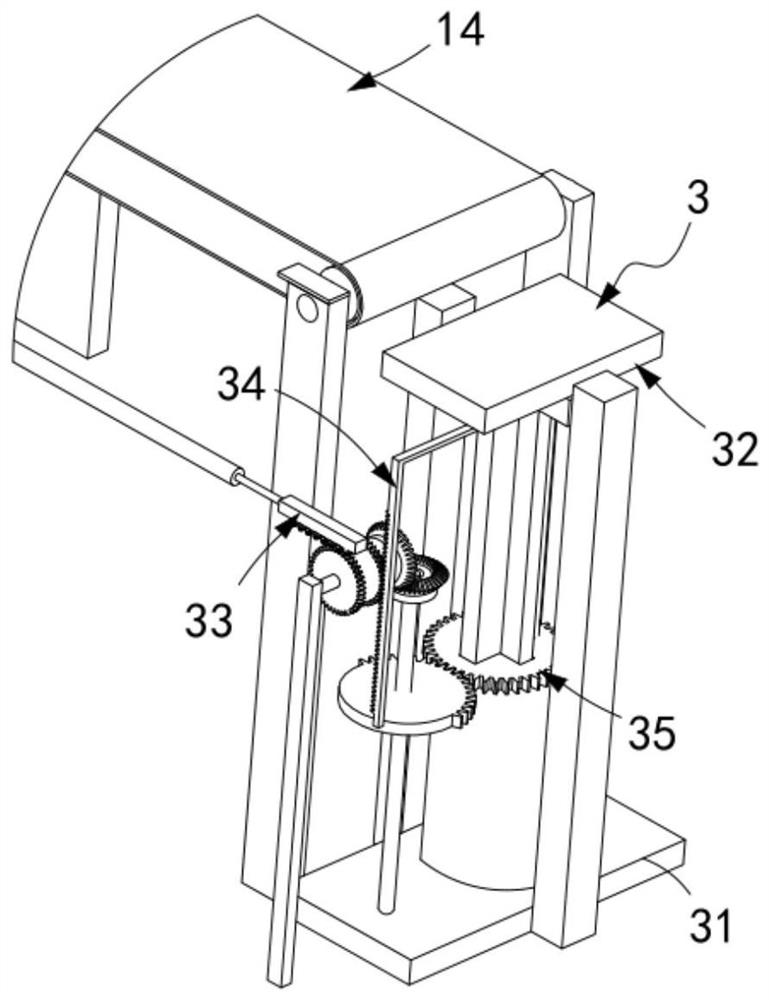
[0049] A stacking mechanism 3, the stacking mechanism 3 is arranged at the output end of the transmission mechanism 1, and it includes a support frame 31 and a tray assembly 32 installed on the support frame 31, which is synchronously driven with the horizontal push assembly 12 The first transmission assembly 33 is driven by the first transmission assembly 33 and is used to drive the down-moving assembly 34 of the connecting plat...

Embodiment 2

[0078] Such as Figure 8 and Figure 9 As shown, the components that are the same as or corresponding to those in the first embodiment are marked with the corresponding reference numerals in the first embodiment. For the sake of simplicity, only the differences from the first embodiment will be described below. The difference between this embodiment two and embodiment one is:

[0079] further, such as Figure 8 and Figure 9As shown, the locking mechanism 4 includes an abutment block 41 fixedly arranged on the connecting column 323, two sets of limit frames 42 correspondingly arranged on one side of the abutment block 41, The length direction of the frame 42 is equidistantly arranged with several groups of elastic buckles 43, the transmission rod a44 fixedly connected to the back of the elastic buckle 43 and arranged horizontally, the transmission rod a44 arranged vertically and fixedly connected with several groups of the described transmission rod a44 b45, the transmissi...


PUM


Abstract

The invention relates to a full-automatic stacking device for sintered bricks. The full-automatic stacking device for sintered bricks comprises a conveying mechanism, a grinding mechanism, a stackingmechanism and clamping mechanisms, wherein the conveying mechanism comprises a rack, a horizontal pushing assembly, a first conveying mechanism and a second conveying mechanism; the grinding mechanismis located between the first conveying assembly and the second conveying assembly; the stacking mechanism comprises a supporting frame, a receiving disc assembly, a first transmission assembly in synchronous transmission with the horizontal pushing assembly, a downward moving assembly driven by the first transmission assembly to conduct transmission and used for driving the receiving disc assembly to move downwards in the vertical direction, a rotating assembly for driving the receiving disc assembly to intermittently rotate, and a lateral moving assembly reciprocating in the horizontal direction, and the receiving disc assembly, the first transmission assembly, the downward moving assembly, the rotating assembly and the lateral moving assembly are installed on the supporting frame; and the two clamping mechanisms are symmetrically arranged on the two sides of the receiving disc assembly, and fixedly installed on the receiving disc assembly. The technical problems that during multi-layer stacking work, a workbench cannot naturally descend, and meanwhile, during multi-group stacking work in the horizontal direction, the horizontal space of a workshop is occupied are solved.

Description

technical field [0001] The invention relates to the technical field of sintered bricks, in particular to an automatic stacking device for sintered bricks. Background technique [0002] In the brick production process of the prior art, after the bricks are fired and formed, they are transported out of the tunnel kiln by the kiln car. After the temperature of the bricks drops to a certain temperature, the bricks need to be transported and stacked from the kiln car. At present, such a process is carried out manually, which is labor-intensive and inefficient, which is not conducive to mechanized production. [0003] The patent document with the patent number CN2019103968816 discloses a fully automatic concrete brick stacking and packaging production line and its working method. The left conventional layer concrete brick conveyor line and the right conventional layer concrete brick conveyor line are used to transport the concrete required for stacking the conventional layer Bric...

Claims


Application Information

Patent Timeline
Patent Type & Authority Applications(China)
IPC IPC(8): B65G57/24B65G57/03B65G49/08
CPCB65G49/08B65G57/035B65G57/24
Inventor 李兵
Owner 李兵
Why Eureka
Try Eureka