Multiple video cameras synchronous quick calibration method in three-dimensional scanning system

A multi-camera, calibration method technology, applied in image analysis, image data processing, instruments, etc., can solve the problems of high manufacturing requirements, complex manufacturing, and inability to achieve simultaneous and rapid calibration of multiple camera parameters.

Inactive Publication Date: 2008-11-05
NANTONG TONGYANG MECHANICAL & ELECTRICAL MFR +1
View PDF0 Cites 81 Cited by
  • Summary
  • Abstract
  • Description
  • Claims
  • Application Information

AI Technical Summary

Problems solved by technology

The disadvantage of this method when applied to the simultaneous rapid calibration of multiple camera parameters is that it requires multiple manual interventions, that is, manually rotate the plane calibration template at a certain angle to shoot multiple images, and the camera can only see the plane at a certain angle Marking points on the template, when the angle between the optical axis of the camera and the plane template is too small, the marking points on it will not be accurately displayed on the camera plane, resulting in the inability to achieve simultaneous and fast calibration of multiple camera parameters
Another common calibration object is the three-dimensional calibration block. The common three-dimensional calibration block is complicated to manufacture and requires high precision, and generally only the surface information of the three planes on the calibration block can be observed.

Method used


Image

  • Multiple video cameras synchronous quick calibration method in three-dimensional scanning system
  • Multiple video cameras synchronous quick calibration method in three-dimensional scanning system
  • Multiple video cameras synchronous quick calibration method in three-dimensional scanning system

Examples


Embodiment Construction

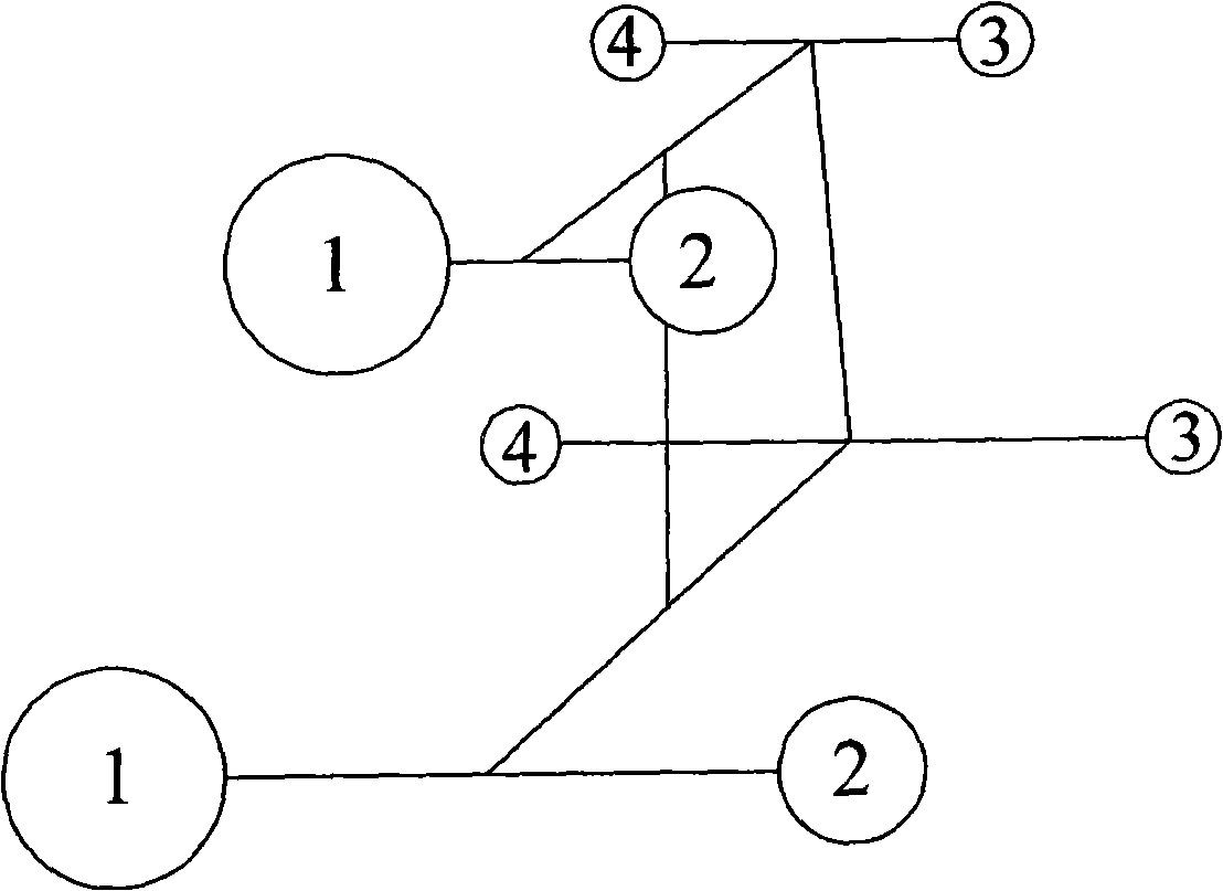
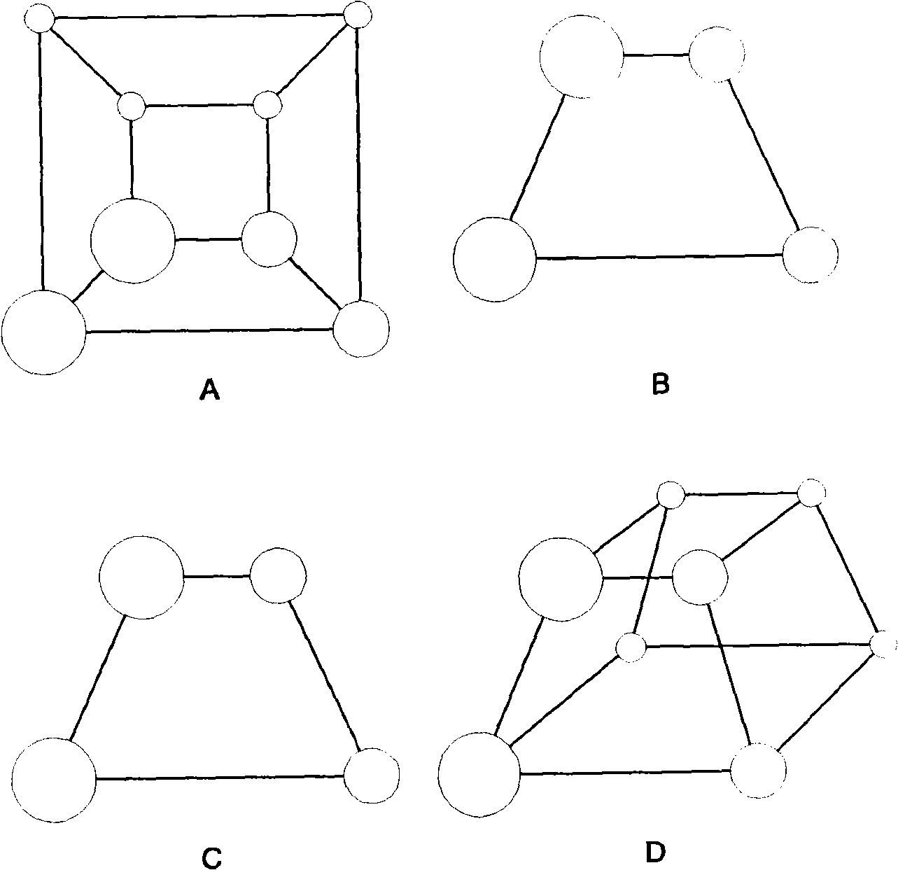
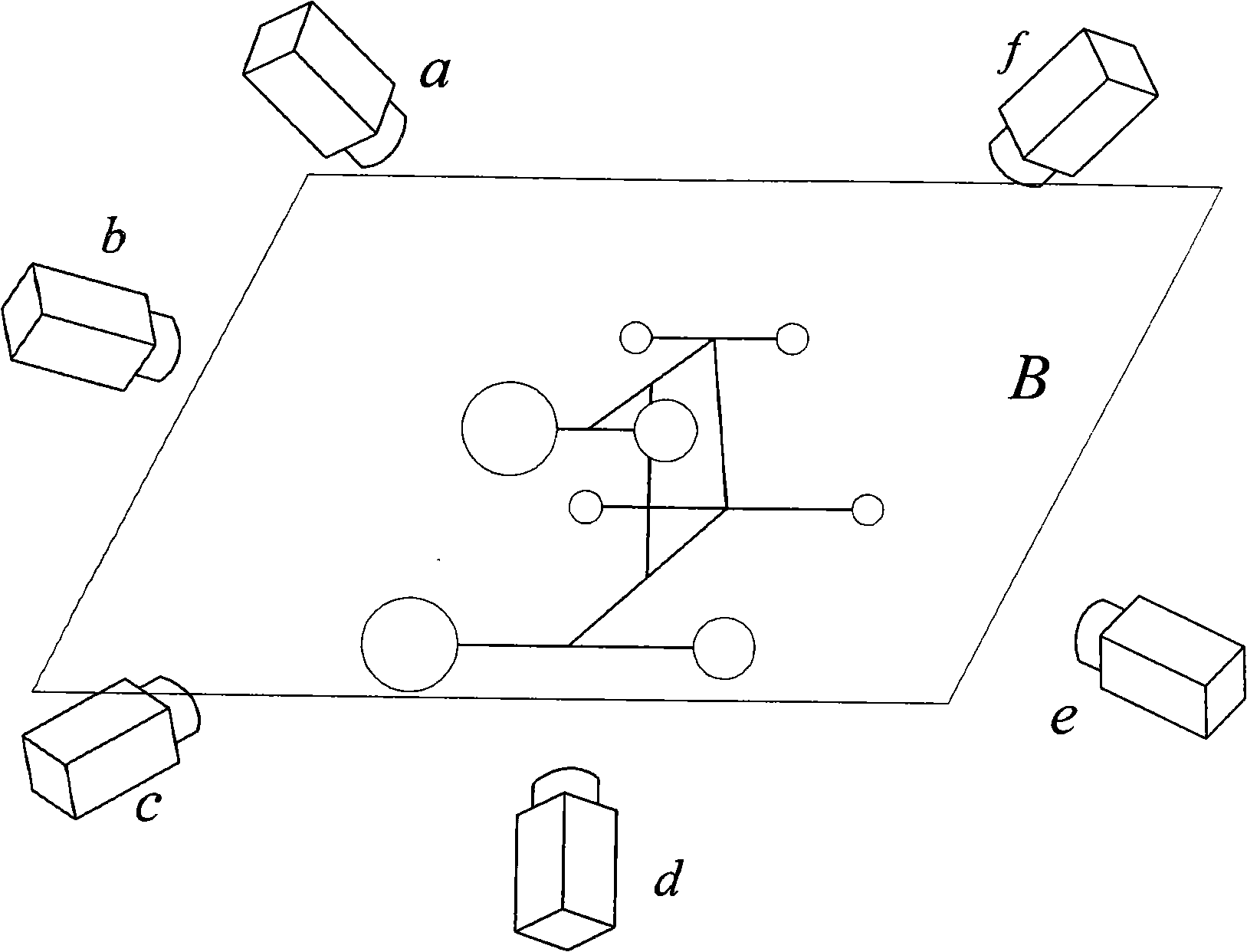
[0049] A synchronous and fast calibration method for obtaining parameters of multiple cameras in a three-dimensional scanning system, including: setting a three-dimensional calibration object, shooting the three-dimensional calibration object, combining with a pinhole perspective model, solving a homography matrix, and obtaining a single camera The internal parameter matrix, external parameter matrix and the initial value of the distortion coefficient, and use the nonlinear optimization method to solve the optimal solution of the parameters of a single camera, put the coordinate systems of multiple cameras in the space into the same camera coordinate system, And the optimal solution of rotation parameter matrix and translation parameter matrix between two cameras is obtained by using epipolar geometric constraint relation.

[0050] Below with reference to accompanying drawing, specific embodiment of the present invention is described in more detail:

[0051] (1) Setting of spa...


PUM


Abstract

A synchronous quick calibration method of a plurality of video cameras in a three-dimensional scanning system, which includes: (1) setting a regular truncated rectangular pyramid calibration object, setting eight calibration balls at the vertexes of the truncated rectangular pyramid, and respectively setting two reference calibration balls at the upper and lower planes; (2) using the video cameras to pick-up the calibration object, adopting the two-threshold segmentation method to respectively obtain the corresponding circles of the upper and lower planes, extracting centers of the circles, obtaining three groups of corresponding relationships between circle center points in the image and the centres of calibration ball in the space, solving the homography matrix to obtain the internal parameter matrix and external parameter matrix and obtaining the distortion coefficient, taking the solved video camera parameter as the initial values, and then using a non-linear optimization method to obtain the optimum solution of a single video camera parameter; (3) obtaining in sequence the external parameter matrix between a plurality of video cameras and a certain video camera in the space, using the polar curve geometric constraint relationship of the binocular stereo vision to establish an optimizing object function, and then adopting a non-linear optimization method to solve to get the optimum solution of the external parameter matrix between two video cameras.

Description

technical field [0001] The invention relates to the calibration of camera model parameters in a vision system, in particular to a method for synchronously fast calibration of multiple camera parameters based on a three-dimensional calibration object in a three-dimensional scanning system. Background technique [0002] One of the basic tasks of computer vision is to calculate the three-dimensional information of the object in the field of view from the image captured by the camera, so as to reconstruct and recognize the three-dimensional object. The relationship between the three-dimensional geometric information of the object surface point and its corresponding point on the image is determined by the imaging model of the camera. The process of establishing this geometric model is actually the solution process of the camera parameters. Therefore, the calibration of camera parameters is the premise and key of this modeling process. The process of solving the camera parameters...

Claims


Application Information

Patent Timeline
Patent Type & Authority Applications(China)
IPC IPC(8): G06T7/00
Inventor 达飞鹏邢德奎傅有成
Owner NANTONG TONGYANG MECHANICAL & ELECTRICAL MFR
Why Eureka
Try Eureka