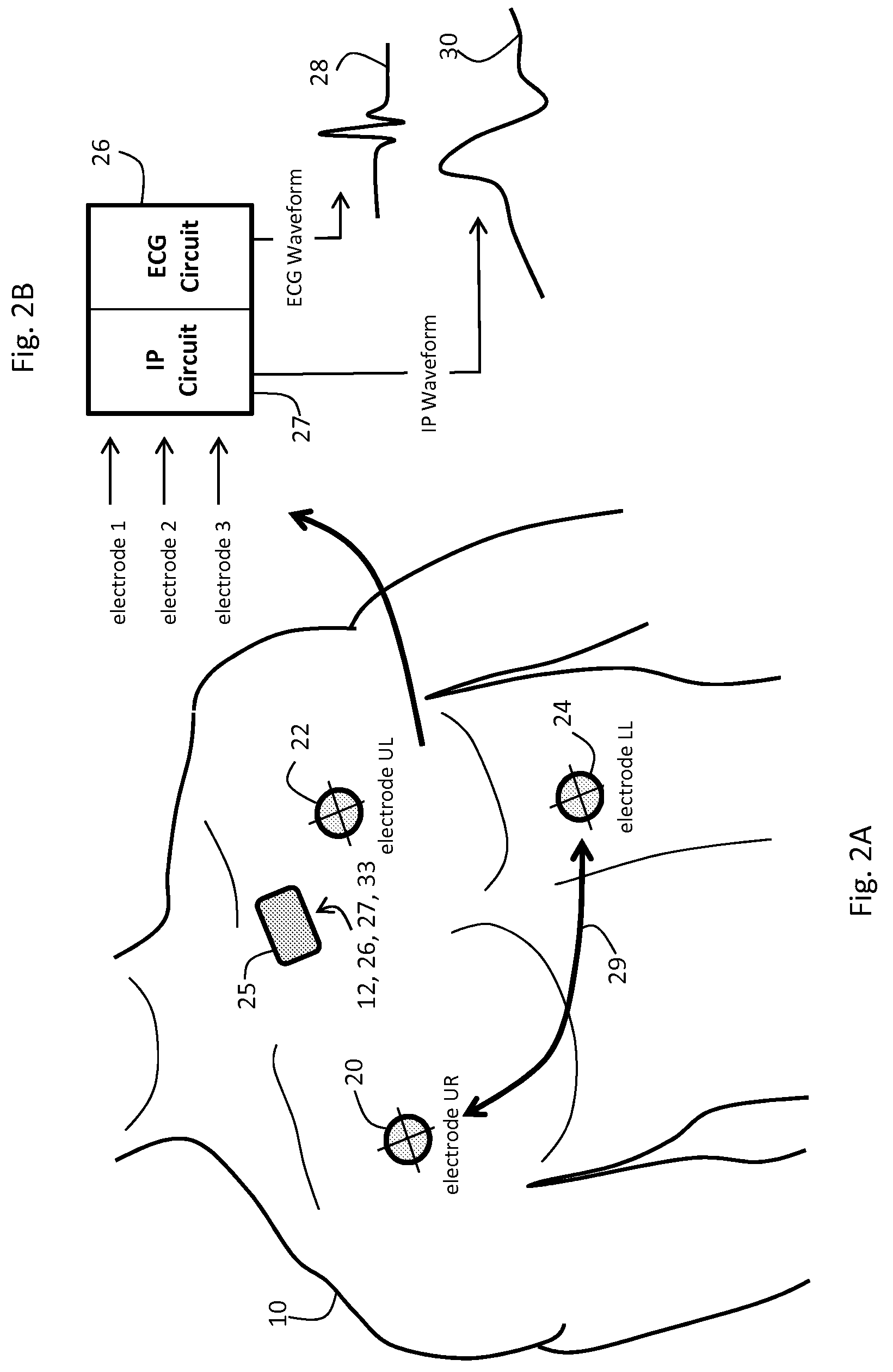
[0012]The body-worn monitor measures IP, PPG, ECG, and ACC waveforms with a series of sensors integrated into a comfortable, low-profile
system that preferably communicates wirelessly with a
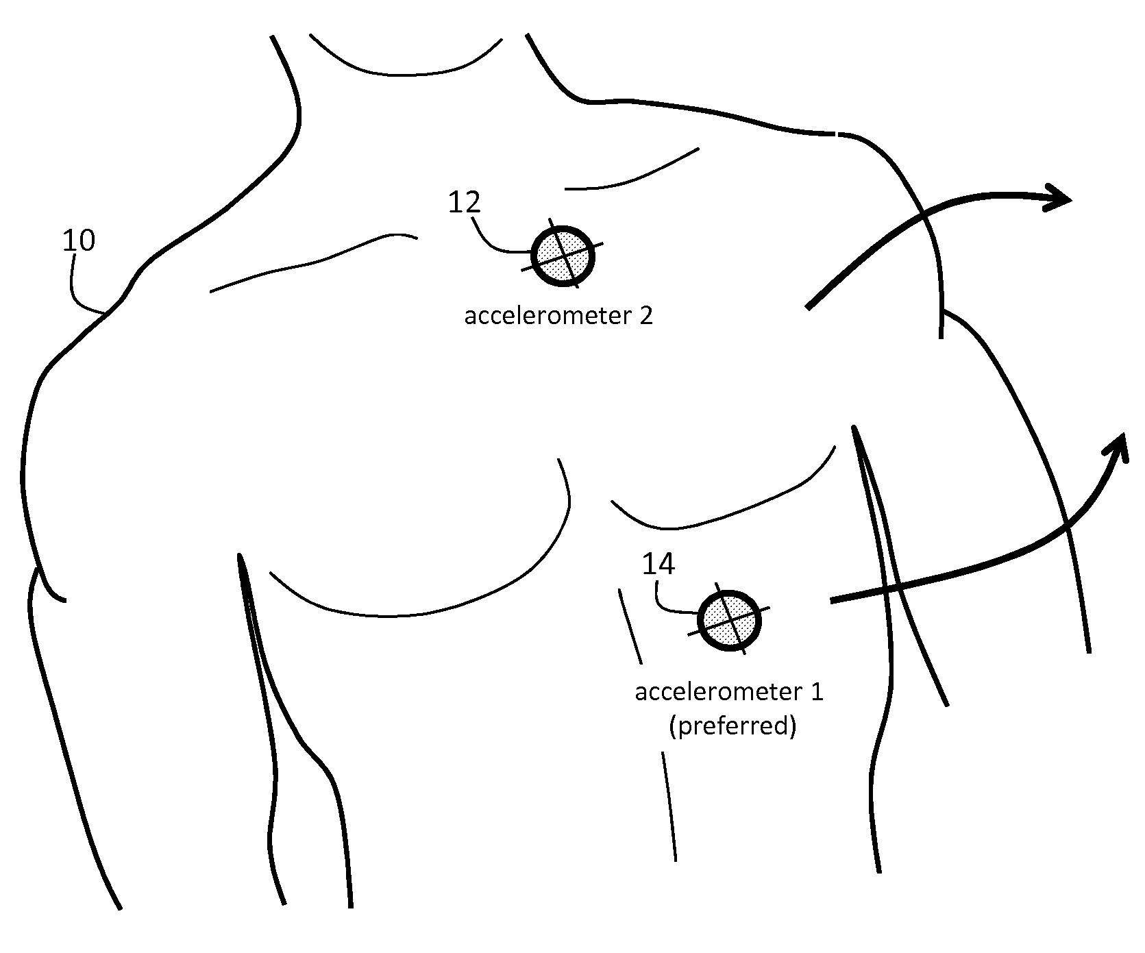
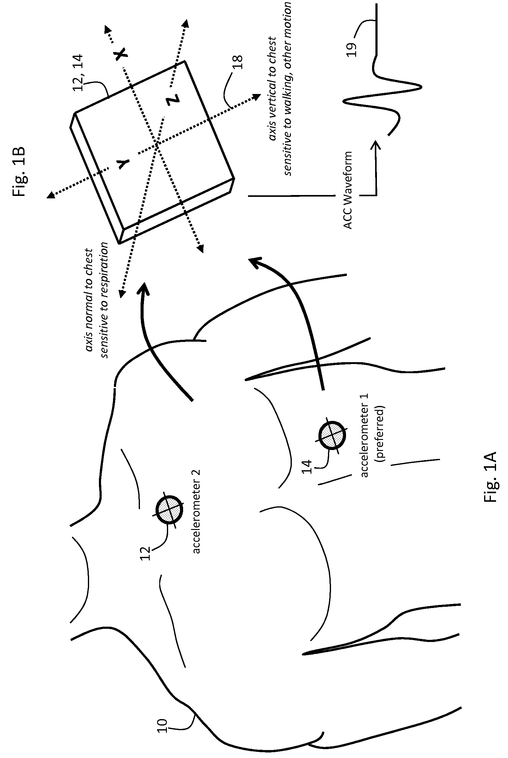
remote computer in the hospital. The system typically features three accelerometers, each configured to measure a unique signal along its x, y, and z axes, to yield a total of nine ACC waveforms. In certain embodiments, the accelerometers are deployed on the patient's
torso, upper arm, and lower arm, and may be embedded in the monitor's cabling or processing unit. Each ACC waveform can be additionally processed to determine the patient's posture, degree of motion, and
activity level. These parameters serve as valuable information that can ultimately reduce occurrences of ‘false positive’ alarms / alerts in the hospital. For example, if processing of additional ACC waveforms indicates a patient is walking, then their RR rate, which may be affected by walking-induced artifacts, can be ignored by an alarm / alert engine associated with the body-worn monitor. The assumption in this case is that a walking patient is likely relatively healthy, regardless of their RR value. Perhaps more importantly, with a conventional monitoring device a walking patient may yield a noisy IP signal that is then processed to determine an artificially high RR, which then triggers a
false alarm. Such a situation can be avoided with an independent measurement of motion, such as that described herein. Other
heuristic rules based on analysis of ACC waveforms may also be deployed according to this invention.
[0015]As described in these applications, the Composite Technique (or, alternatively, the ‘
Hybrid Technique’ referred to therein) typically uses a single PPG waveform from the SpO2 measurement (typically generated with
infrared radiation), along with the ECG waveform, to calculate a parameter called ‘
pulse transit time’ (PTT) which strongly correlates to
blood pressure. Specifically, the ECG waveform features a sharply peaked QRS complex that indicates
depolarization of the heart's left
ventricle, and, informally, provides a time-dependent marker of a
heart beat. PTT is the time separating the peak of the QRS complex and the onset, or ‘foot’, of the PPG waveforms. The QRS complex, along with the foot of each pulse in the PPG, can be used to more accurately extract AC signals using a mathematical technique described in detail below. In other embodiments both the red and
infrared PPG waveforms are collectively processed to enhance the accuracy of the cNIBP measurement.
[0022]In another aspect, the invention provides a system for monitoring a patient's RR that also accounts for their posture,
activity level, and degree of motion. Such patient states can result in artifacts that affect the RR measurement, and thus proper interpretation of them can reduce the occurrence of erroneous RR values and ultimately false alarms / alerts in the hospital.
[0030]Many advantages are associated with this invention. In general, it provides an accurate measurement of RR, along with an independent measurement of a patient's posture,
activity level, and motion, to characterize an
ambulatory patient in the hospital. These parameters can be collectively analyzed to improve true positive alarms while reducing the occurrence of false positive alarms. Additionally, the measurement of RR is performed with a body-worn monitor that is comfortable, lightweight, and low-profile, making it particularly well suited for patients that are moving about. Such a monitor could continuously monitor a patient as, for example, they transition from the
emergency department to the ICU, and ultimately to the home after hospitalization.

